Epm electric power manager – C.E. Niehoff & Co. N1387-1/EPM Troubleshooting Guides User Manual
Page 10
Page 10
TG0019A
Pin
Function
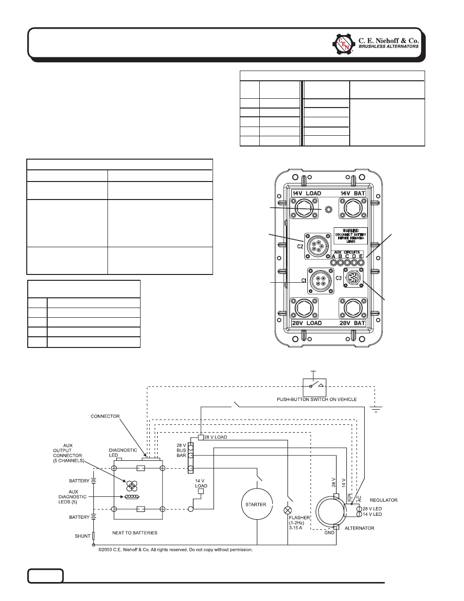
TABLE 7 – EPM Harness Plug
Socket Functions
A
B
C
D
Battery Ground
Alternator Phase In Signal
Energize (Active Low) Signal
Ignition Signal
Figure 10 – EPM System Schematic
EPM Electric Power Manager
DESCRIPTION AND OPERATION
Main diagnostic feature of the EPM is a bicolored
(amber, green) LED located on the side of the device.
The EPM manually connects and automatically
disconnects batteries after 3 minutes unless emer-
gency flashers are on.
EPM also allows batteryless operation until vehicle is
shut off.
Section 6: Troubleshooting the EPM
Figure 9 – EPM Electric Power Manager
T T T T T
J1939
Connector
Under Cap
(see p. 4 for
details)
TTTTT
EPM LED
TTTTT
EPM
Connector
TTTTT
AUX
Circuits
Connector
T T T T T
Aux. Load
Diagnostic
LEDs
EPM LED COLOR
EPM STATUS
TABLE 6 – EPM LED Diagnostics
EPM is not energized or EPM is
defective.
Off (Clear)
Flashing GREEN
Steady GREEN
EPM has connected the batteries
during start-up and has prevented
automatic disconnection for 3
minutes after vehicle shuts down
when only vehicle battery-connect
button is pressed.
Normal operation (batteries are
connected to the system and
engine is running)
Pin
Function
(Max. 30 A)
TABLE 8 – AUX Circuit and LED Functions
A
B
C
D
E
14 V
28 V
28 V
28 V
28 V
EPM
EPM
EPM
N3225
N1387-1
LED Color
Normally On
If LED
OFF:
GREEN
GREEN
GREEN
GREEN
GREEN
A short or overcurrent
may have occurred.
Check AUX load wiring
and reset EPM by
pressing Low Battery
Indicator.