Can/j1939 interface – C.E. Niehoff & Co. N1387-1/EPM Troubleshooting Guides User Manual
Page 4
Page 4
TG0019A
Section 3: CAN/J1939 Diagnostics
CAN/J1939 Interface
DESCRIPTION AND OPERATION
The EPM and the CEN N3225 digital regulator are compatible with the
SAE J1939 communications standard for vehicle networking.
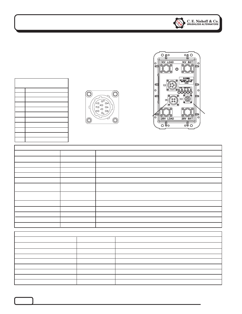
CEN uses MIL-STD connector MS3112E12-10P to interface between the
EPM/N3225 and the DPA adapter used to monitor the broadcast
messages on the CAN bus line. The readouts of these messages are
shown in Table 2 for the EPM and Table 3 for the regulator.
Pin
Identification
TABLE 1 – J1939 Connector
Circuit Identification
A
B
C
D
E
F
G
H
J
K
CAN High
CAN Low
CAN Shield
Ground
Restricted use
Restricted use
Restricted use
unused
unused
+28V power
Figure 4 – EPM Electric Power Manager
T T T T T
J1939
Connector
Under Cap
T
T
T
T
T
EPM
Connector
to N3225
Regulator
EPM Readout
Expected Reading
TABLE 2 – EPM/J1939 Readout Diagnostics (With Engine Running)
Load Voltage 28 V System
Load Voltage 14 V System
Alternator Speed
Battery Voltage 28 V System
Battery Voltage 14 V System
EPM Temperature
Charging and Discharging
Current of 28 V Battery
Batt Charging 28 V LED
Batt Charging 14 V LED
Main Switches On
Cranking Detected
Emergency Flasher Detected
Figure 3 – J1939
Connector Pins
27–29 V
13.5–14.5 V
1200 to 6000 RPM
27–29 V
13.5–14.5 V
–50ºF (–46ºC) to
200ºF (93ºC)
10 A (varies according
to battery condition)
OK
OK
OK
OK
OK
Action If Expected Reading Not Achieved
See Chart 1, page 7.
See Chart 2, page 8.
Check drive belt and charging system connection.
See Chart 1, page 7.
See Chart 2, page 8.
Check connections to EPM.
Observe current charges with battery and ignition on and then off.
See Chart 1, page 7.
See Chart 2, page 8.
Verify “Battery Connect” indicator is lit AMBER.
See Chart 5, page 11.
Check bulbs on flashers or ICC to battery.
Regulator Readout
Expected Reading
TABLE 3 – N3225 Regulator/J1939 Readout Diagnostics
Alternator Output Voltage 28 V System
Alternator Output Voltage 14 V System
Alternator Speed
Alternator Temperature
Battery Voltage 28 V System
Battery Voltage 14 V System
Alternator Output Capacity
Charging System Status
27–29 V
13.5–14.5 V
1200 to 6000 RPM
Less than 260º F/127ºC
27–29 V
13.5–14.5 V
0–100%
OK
Action If Expected Reading Not Achieved
See Chart 1, page 7.
See Chart 2, page 8.
Check drive belt and chg system connection.
Decrease load on alternator. See Chart 4, page 9.
See Chart 1, page 7.
See Chart 2, page 8.
Varies with load.
See Chart 1, page 7, or Chart 2, page 8.