Caution – C.E. Niehoff & Co. N1304-1 to N1380-2: N7359-1 Conversion Kit Instructions User Manual
Page 3
Page 3
II0063A
CAUTION
10. Remove two top nuts on B+ stud and discard
one nut. Install output lead and remaining nut
on B+ stud and tighten firmly enough to hold
output lead on stud.
Out put terminal may
be damaged if nut is
overtightened.
11. Connect stator leads and phase lead to proper
stator terminals as shown in Figure 2. Torque
hardware to 3.4 Nm/30 lb. in.
12. Coat stator terminals and terminal block and
B+ stud terminal inside control unit with Dow
Corning
®3
3140 RTV coating or equivalent. Do
not use coating containing acetic acid (vinegar
smell) on electrical components.
13. Install new control unit cover on control unit
with tab on top facing out. Use a suitable adhe-
sive, such as Loctite
®
222 on new hardware.
Follow manufacturer’s instructions. Torque
screws to 2-2.25 Nm/18-20 lb. in.
14. Remove and discard two existing screws on top
of control unit.
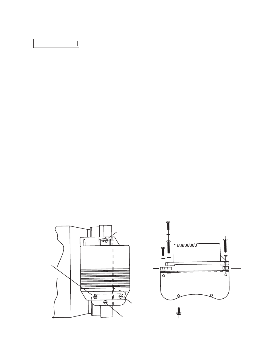
15. Place bracket, spacer, and regulator on top of
control unit as shown in Figure 5.
16. Use a suitable adhesive, such as Loctite
®
222 on
new hardware. Follow manufacturer’s instruc-
tions. Loosely install (see Figure 5):
a. one long screw and washer in regulator
mounting hole above spacer.
b. remaining long screw and washer in front
regulator mounting hole above bracket.
c. one short screw and washer in rear regulator
mounting hole above bracket.
d. remaining short screw and washer in
bracket.
17. Torque screws in a-b-c-d order listed in step 16
to 2-2.25 Nm/18-20 lb. in.
18. Place ADE rotor on shaft. Align scribe mark.
Loosely install all nuts and washers except for
the nut for the marked hole. Before securing
nuts, make sure scribe mark in last hole is
aligned. Then secure all nuts. On all screws, use
a suitable adhesive, such as Loctite
®
222.
Follow manufacturer’s instructions.Torque to
3.4 Nm/30 lb. in.
19. Align scribed marks, then set ADE housing
assembly in position on shell. If bearing re-
mained in housing, use CEN A10–109 bearing
tool or equivalent placed on bearing inner race.
Press on bearing and guide ADE housing on
shell. Rotate shaft to make sure bearing moves
freely.
20. Install existing locknuts on through-studs. Use
a suitable adhesive, such as Loctite
®
222.
Follow manufacturer’s instructions. Torque
locknuts to 2-2.25 Nm/18-20 lb. in.
21. Press fan assembly into bore of ADE housing.
Fasten with existing hardware and torque to
67.8 Nm/50 lb. ft.
22. Install pulley bushing on drive end shaft with
short hub facing bearing.
23. Install Woodruff key in slot in shaft.
24. Install pulley on shaft. Torque to 162.7 Nm/
120 lb. ft.
25. Plug regulator harness plug into regulator
receptacle in housing.
Test unit on bench to verify proper operation
after assembling.
TTTTT
Long
screw
Figure 5—New Regulator and Bracket Assembly
TTTTT
Short
screw
TTTTT
Bracket
TTTTT
Spacer
Long screw -
step 16a
T T T T T
Long screw -
step 16b
T T T T T
Short screw -
step 16c
T
T
T
TT
Short screw -
step 16d
T T T T T