C.E. Niehoff & Co. N1304-1 to N1380-2: N7359-1 Conversion Kit Instructions User Manual
C. e. niehoff & co, Conversion instructions
Page 1
II0063A
N1304-1 Alternator to N1380-2 Alternator
Conversion Instructions
C. E. Niehoff & Co.
BRUSHLESS ALTERNATORS
Using N7359-1 Conversion Kit
Disassembly
1. To make reassembly easier, mark the following
junctions:
a. anti-drive end housing and shell.
b. drive end housing and shell. Transfer the
mark from the existing drive end housing
to the same location on the new drive end
housing.
2. Remove and save pulley (if installed), Woodruff
key, and pulley bushing on drive end.
3. Remove and discard:
a. regulator hardware and regulator.
b. control unit front cover hardware and
control unit front cover.
3. Remove and save nut and washer holding fan on
anti-drive end of shaft. Remove and save fan.
4. Remove and save nuts holding anti-drive end
housing. Remove and save anti-drive end
housing. Bearing and seals should remain
on shaft.
5. Remove and save one nut and washer from
anti-drive end rotor. Mark across middle of
hole on face of rotor to realign rotor on shaft
core. Remove and save remaining nuts and
washers, then remove and save rotor.
a. To loosen rust, use an air chisel with a
rounded-point hammer bit to vibrate area
between screw holes on rotor face.
— OR—
The following terms are used to bring attention to the presence of hazards of various risk levels or to important information
concerning product life.
NOTICE
Indicates the presence of
hazards that will or can cause
minor personal injury or property
damage if ignored.
CAUTION
Indicates special instructions on
installation, operation, or main-
tenance that are important, but
not related to personal injury
hazards.
NOTICE
All hardware should be saved
for reuse unless otherwise
noted.
CAUTION
b. Use three 10-32 jacking screws to lift rotor
off core.
This method may
damage rotor if rotor
is rusted to core.
6. Inside control unit, remove coating material
covering three terminal leads and B+ stud.
7. Remove hardware holding three terminal leads
and B+ stud. Remove the three leads and the
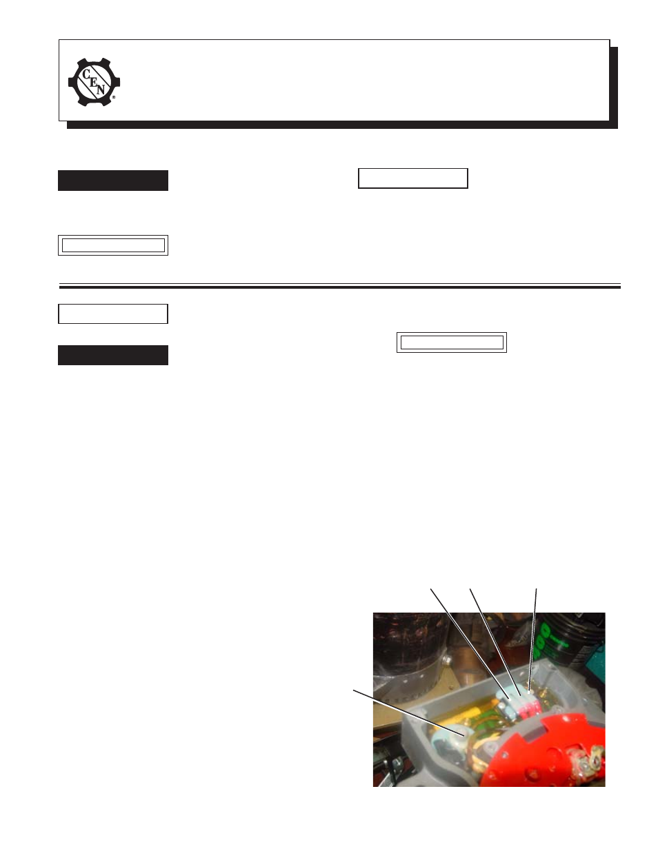
leads from the B+ stud. See Figure 1.
8. Mark leads for reassembly and carefully pull
three terminal leads from coating material so as
not to damage leads. Clean coating material from
leads. Check terminals for rust or corrosion and
clean with wire brush if necessary.
9. Remove output lead attached to B+ stud.
Indicates the presence of
hazards that will cause severe
personal injury, death, or
substantial property damage if
ignored.
DANGER
Do not allow hardware to drop
inside alternator. Loose hard-
ware inside alternator cavity or
stator windings or field coil
will cause substantial
equipment damage.
DANGER
Figure 1—Control Unit Connections
B+ stud and
output lead
from heat
sink
TTTTT
T
T
T
T
T
T
T
T
T
T
T
T
T
T
T
Ground terminal
lead from heat
sink
F–
terminal lead
F+
terminal lead