Assembly, Caution – C.E. Niehoff & Co. N1304-1 to N1380-2: N7359-1 Conversion Kit Instructions User Manual
Page 2
II0063A
Page 2
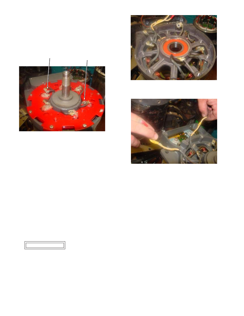
10. Remove and save hardware holding stator leads
and phase lead (attached to stator lead (at 10:00
position) to heat sink assembly. See Figure 2.
Clean coating material from leads. Check termi-
nals for rust or corrosion and clean with wire
brush if necessary.
11. Remove and save heat sink hardware (including
ground bolt and lockwasher on tab on side of
housing) and heat sink assembly.
12. Remove and save drive end housing hardware.
13. Remove drive end housing from shell.
14. Press shaft out of bearing in drive end housing.
Discard drive end housing and bearing. Save
shaft core/drive end rotor assembly.
Assembly
1. New drive end housing has bearing and retaining
rings installed at factory. Using CEN A10–109
bearing tool or equivalent placed on bearing
inner race, press shaft into bearing in DE
housing. Rotate shaft to make sure bearing
moves freely.
2.
Support shell/field coil/stator assembly on
blocks while installing DE housing and shaft.
Do not damage stator
windings or through-studs
while assembling DE hous-
ing and shell. Make sure
support is tall enough so
that shaft clears bench.
3.
Align scribed marks, then set housing assembly
in position. Pull stator leads and field coil leads
through vent holes in assembly. See Figures 3
and 4. Securely mate housing to shell. Rotate
shaft to make sure rotor does not interfere with
stator leads or field coil leads.
Figure 2—Phase Lead and Stator Leads Connections
T
T
T
T
T
T
T
T
T
T
Stator lead
(one of six)
T
T
T
T
T
T
T
T
T
T
Phase lead
CAUTION
4.
Install existing locknuts on through-studs. Use
a suitable adhesive, such as Loctite
®
222.
Follow manufacturer’s instructions. Torque
locknuts to 2-2.25 Nm/18-20 lb. in.
5.
Guide field coil leads through channel in hous-
ing. See Figure 2. Attach field coil leads to
terminal block. See Figure 1 for correct loca-
tions. Tighten screws just enough to firmly hold
leads in terminal block. Wire-tie field coil leads
together inside channel.
6.
Install heat sink assembly, guiding stator leads
and phase lead through center opening to their
respective positions. See Figure 2.
7.
Install existing hardware to hold heat sink in
position. Use a suitable adhesive, such as
Loctite
®
222. Follow manufacturer’s instruc-
tions. Torque screws to 2-2.25 Nm/18-20 lb. in.
8.
Loosely install ground bolt and lockwasher in
tab on side of heat sink into housing.
9.
Install ground lead in terminal block. Tighten
screw just enough to firmly hold leads in termi-
nal block. See Figure 1 for position.
Figure 3—Phase Leads and Field Coil Leads
Figure 4—Field Coil Leads