Troubleshooting, Internal circuit tests, Caution – C.E. Niehoff & Co. C130/C131/C132 Inst/Parts Rep/TG Combo Guide User Manual
Page 9: Notice
Page 9
SM40A
Troubleshooting
(CONT’D)
Internal Circuit Tests
• Internal Circuit Tests will show the condition of
internal circuits through the alternator via alternator-
to-regulator harness.
• Some disassembly will be necessary to access the
components. Do not disassemble the alternator
beyond what the tests require.
• Before performing Internal Circuit Tests, check for
visible signs of damaged components.
• The expected reading/result listed for each test must
be obtained. Replace any component that fails the test.
CAUTION
Failure to perform the complete
series of Internal Circuit Tests can
result in improper diagnosis of
alternator
condition.
Service technicians should
understand and follow all
information in the service manual
when servicing the product.
NOTICE
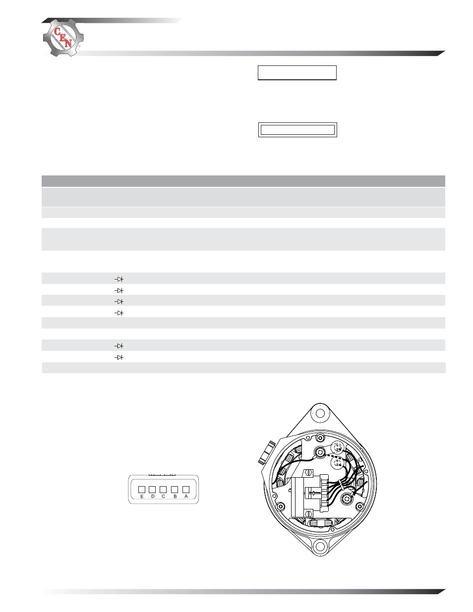
TABLE 3 Pin-to-Pin Tests (See Figure 4)
* Applies only when field coil is attached to rectifier/housing assembly.
METER (+) LEAD
CONNECTION
Socket A
Socket E
Socket E
Socket E
Socket C
Socket C
Socket D
Alt. B+ Terminal
Socket D
Alt. B– Terminal
Socket E
Socket A
Alt. B+ Terminal
Alt. B– Terminal
R Terminal
METER (–) LEAD
CONNECTION
Alternator Case
Socket C
Alt. B– Terminal
Alternator Case
Alt. B– Terminal
Alternator Case
Alt. B+ Terminal
Socket D
Alt. B– Terminal
Socket D
Alt. B+ Terminal
Alt. B– Terminal
Alt. B– Terminal
Alt. B+ Terminal
Alternator Case
TESTED CIRCUIT
Isolated ground
Field coil resistance
Field coil insulation
Field coil insulation
Field coil insulation
Field coil insulation
Phase winding and diode
Phase winding and diode
Phase winding and diode
Phase winding and diode
Regulator power circuit
Regulator ground circuit
All diodes in parallel
All diodes in parallel
Stator insulation
EXPECTED
READING
OL (infinity)
4.8±0.2 ohms
OL (infinity)
OL (infinity)
OL (infinity)
OL (infinity)
<0.7 volts (flow)
OL (blocking)
OL (blocking)
<0.7 volts (flow)
0 ohms
0 ohms
OL (blocking)
<0.8 volts (flow)
OL (infinity)
TEST
NO.
1
2*
3
4
5
6
7
8
9
10
11
12
13
METER SCALE
& SYMBOL
Ohms Ω
Ohms Ω
Ohms Ω
Ohms Ω
Ohms Ω
Ohms Ω
Diode Test
Diode Test
Diode Test
Diode Test
Ohms Ω
Ohms Ω
Diode Test
Diode Test
Ohms Ω
Figure 4 Alternator Connections
CONNECTIONS
A
B–
B
IGN
C
F–
D
Phase (R)
E
B+
Alternator-to-Regulator Harness Connector
R
B+
IGN
B
−
AB
C
DE