Troubleshooting, Tools and equipment for bench testing, Bench tests – C.E. Niehoff & Co. C130/C131/C132 Inst/Parts Rep/TG Combo Guide User Manual
Page 8: Notice, Caution, Regulator test, Tools and equipment for static testing
Page 8
SM40A
Troubleshooting
Tools and Equipment for Bench Testing
• Testing Electrical Components, page 12.
• Digital Multimeter (DMM)
• Ammeter (digital, inductive)
• Test bench with 5–10 hp motor able to drive
alternator to 8000 rpm. Mount alternator per test
bench manufacturer’s instructions. Make sure test
bench batteries are charged at 95% or higher.
Bench Tests
• Voltage at regulator setpoint ±0.2 V is considered
“normal.”
• Alternator rated output (listed on nameplate) ±10%
is determined at 5000 rpm at 72ºF.
• Run alternator for 15 minutes to stabilize readings.
• Alternator/regulator should be connected to test
bench per schematic diagram on page 3.
When connecting alternator to
test bench, make sure batteries
are connected per schematic
diagram on page 3.
Alternator/regulator will not
function without being properly
connected to power source.
NOTICE
BENCH TEST 1: NO-LOAD TEST
With battery connected and nominal electrical load
set as shown in Table 1, run alternator at 2000-2500
rpm shaft speed.
• If alternator passes No-Load Test, go to Full Load
Test.
• If alternator fails No-Load Test, go to Static Tests.
CAUTION
TABLE
1 No-Load Test
28V
ALT.
AMPS VOLTS
C130
C132
5-40
28±0.2
C131
5-40
14±0.2
BENCH TEST 2: FULL LOAD TEST
With battery connected and electrical load set as
shown in Table 2, run alternator at 5000-8000 rpm
shaft speed.
• If alternator
passes Full Load Test, alternator is
functioning properly.
• If alternator
fails Full Load Test, go to Static Tests.
TABLE 2 Full Load Test
28V
ALT.
AMPS VOLTS
C130
C132
60
28±0.2
C131
70
14±0.2
Regulator Test
• Regulator tester tests all regulator functions.
• If regulator tester is used, follow regulator tester
manufacturer’s instructions.
• If regulator tester is not available, regulator can
only be tested for a shorted field-switching tran-
sistor. Follow Regulator Test below.
REGULATOR TEST: CHECK FOR SHORTED FIELD-
SWITCHING TRANSISTOR
1. Set DMM to diode test scale.
2. See Figure 3. Connect one meter lead to pin C in
regulator receptacle and connect other lead to
pin A in regulator receptacle. Observe meter read-
ing. Reverse leads and observe meter reading. If
DMM reads zero in either direction, field-switching
transistor is shorted. Replace regulator. If regulator
failure is indicated, field coil failure must also be
suspected.
Tools and Equipment for Static Testing
• Testing Electrical Components, page 12.
• Digital Multimeter (DMM)
• Ammeter (digital, inductive)
• Regulator tester
Alternators should not be powered
during static tests. Connections
required during testing can cause
shorts and damage alternator.
Static tests should confi rm
on-vehicle and on-bench tests.
NOTICE
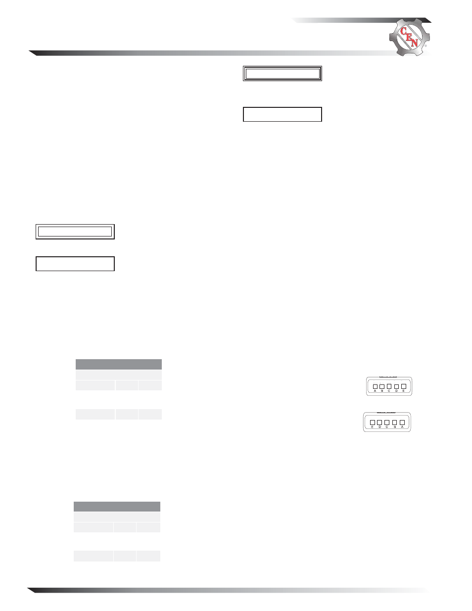
Figure 3 Regulator Harness Connections
WARNING
CONNECTIONS
A
B–
B
IGN
C
F–
D
Phase (R)
E
B+
Regulator Receptacle
Alternator-to-Regulator
Harness Plug