Fuses, 1 fuses within the actuator controls, Fuses 52 – AUMA Electric multi-turn actuators SA 07.1 - 16.1_SAR 07.1 - 16.1 MATIC AM 01.1 - 02.1 User Manual
Page 52
23.
Fuses
.
Switch off the mains before changing the fuses.
.
When replacing fuses, only fuses according to table 13 may
be used.
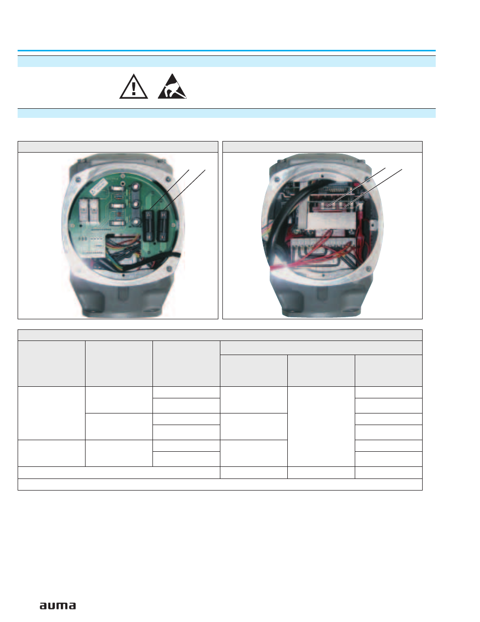
23.1 Fuses within the actuator controls
Fuses (figures AP and AO) are accessible after removal of the local controls.
F1/ F2:
Primary fuses on power supply unit
F3:
Internal 24 V DC supply, RWG, logic board
F4:
Internal 115 V AC supply (optional: 24 V AC);
Heater, tripping device for PTC thermistors,
control of reversing contactors, remote operation
.
After replacing the fuses, screw local controls back on again.
52
Multi-turn actuators SA 07.1 – SA 30.1/ SAR 07.1 – SAR 30.1
with actuator controls AUMA MATIC AM 01.1 / AM 02.1
Operation instructions
Figure AO: Fuses on power supply board
F3
F4
Switchgear
Voltage supply
(mains voltage)
Voltage output
(power supply unit)
G fuses:
(figures
AP
and
AO
)
F 1/F 2
(Board A20, refer to
wiring diagram)
F 3*
)
(Boards A2, refer to
wiring diagram)
F 4*
)
(Boards A8, refer to
wiring diagram)
Reversing
contactors
≤
500 V
24 V
1 A T; 500 V
AUMA article no.:
K002.277
500 mA T; 250 V
1.6 A T; 250 V
115 V
0.4 A T; 250 V
> 500 V
24 V
2 A FF; 660 V
AUMA article no.:
K002.665
1.6 A T; 250 V
115 V
0.4 A T; 250 V
Thyristors
≤
500 V
24 V
16 A FF; 500 V
AUMA article no.:
K001.189
1.6 A T; 250 V
115 V
0.4 A T; 250 V
Size
6.3 x 32 mm
5 x 20 mm
5 x 20 mm
*) according to IEC 60127-2/III
Table 13
Figure AP: Fuses on signal and control board
1F2
1F1