AUMA Electric multi-turn actuators SA 07.1 - 16.1_SAR 07.1 - 16.1 MATIC AM 01.1 - 02.1 User Manual
Page 46
21.7 Positioner adjustment end position CLOSED (inverse operation)
.
Run actuator with push button
(local controls) to
end position CLOSED.
.
Connect voltmeter to measuring points MP2 and MP1 for measuring the
actual value E2:
When position feedback is set correctly, the voltmeter shows 5 V.
If measured value is not correct:
Adjust position feedback according to clauses 16. and 17. and repeat
“positioner adjustment”.
.
Connect max. command signal (nominal value E1) = 20 mA.
.
Connect voltmeter to measuring points MP4 and MP3 for measuring the nomi-
nal value E1:
For a nominal value of 20 mA, the voltmeter shows 5 V.
If measured value is not 5 V:
Check the externally supplied command signal E1.
46
Multi-turn actuators SA 07.1 – SA 30.1/ SAR 07.1 – SAR 30.1
with actuator controls AUMA MATIC AM 01.1 / AM 02.1
Operation instructions
If
LED display:
(refer to figures AH and AJ)
Then
Required setting in end position CLOSED:
(refer to figures AH and AJ)
the LEDs are not illuminated
Turn potentiometer “max” (P4) slowly counterclockwise until
LED
(V27 yellow) is illuminated
LED
(V27 yellow)
is illuminated
Turn potentiometer “max” (P4) clockwise until LED
(V27 yellow)
is no longer illuminated.
Then turn potentiometer “max” (P4) slowly counterclockwise until
LED
(V27 yellow) is illuminated.
LED
(V28 green)
is illuminated
Turn potentiometer “max” (P4) slowly counterclockwise until the
LED
(V28 green) is no longer illuminated and
LED
(V27 yellow) is illuminated.
Table 11
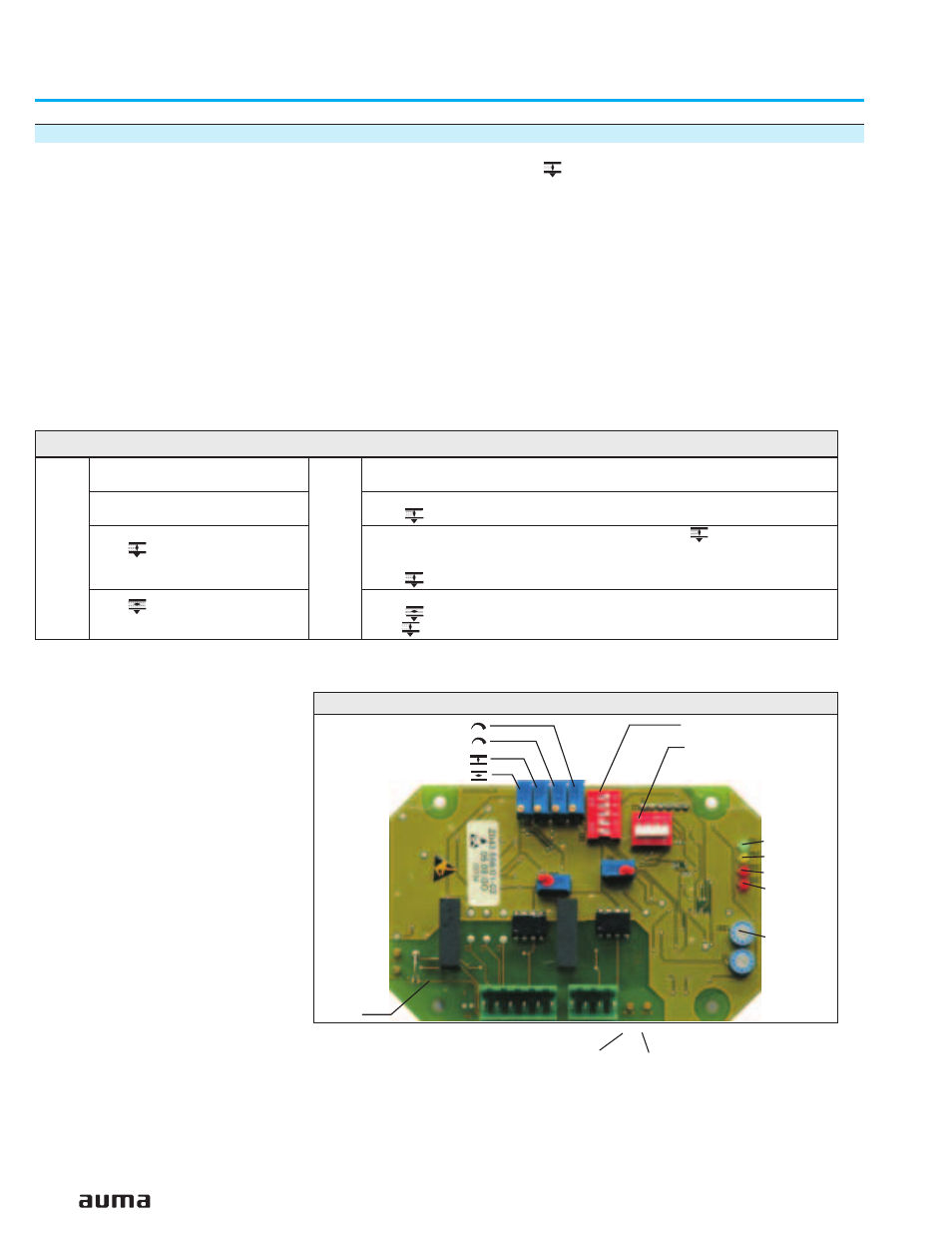
Figure AJ: Positioner board A7
V28
V27
V18
V10
P10
MP2(+)
MP1(–)
S1-7
P9 (
Δ
E)
P7 (Sens)
P3 (0)
P4 (max)
S2-7
S3-7
Meas.
points:
Measuring points: MP3(+)/MP4(–) for E1