Setting the torque switching, 1 setting, 2 checking the torque switches – AUMA Electric multi-turn actuators SA 07.1 - 16.1_SAR 07.1 - 16.1 MATIC AM 01.1 - 02.1 User Manual
Page 25: Torque setting 25, Tripping torque 25
14.
Setting the torque switching
14.1 Setting
.
The set torque must suit the valve!
.
This setting must only be changed with the consent of the
valve manufacturer!
.
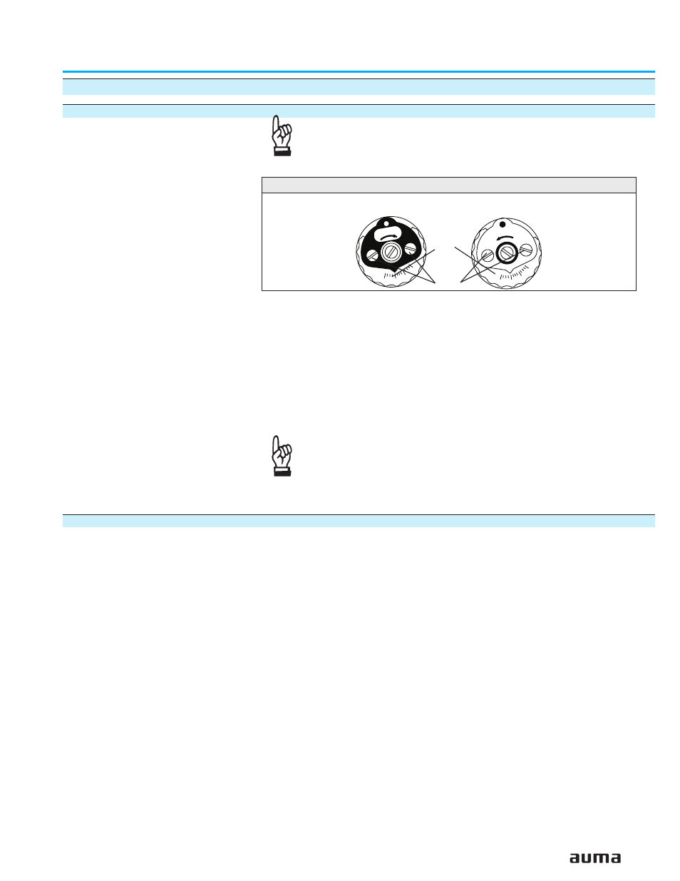
Loosen both lock screws O at the torque dial (figure Q).
.
Turn torque dial P to set it to the required torque.
Example:
Figure Q shows the following setting:
35 ft lbs for direction CLOSE
25 ft lbs for direction OPEN
.
Tighten lock screws O again
.
The torque switches can also be operated in manual
operation.
.
The torque switching acts as overload protection over full
travel, also when stopping in the end positions by limit switch-
ing.
14.2 Checking the torque switches
The red test buttons T and P (figure P-1) are used for manual operation of the
torque switches:
.
Turning T in direction of the arrow TSC (DSR) triggers torque switch
CLOSED.
The yellow indication light (fault) on the local controls is illuminated.
.
Turning P in direction of the arrow TSO (DÖL) triggers torque switch OPEN.
The yellow indication light (fault) on the local controls is illuminated.
.
If a DUO limit switching (optional) is installed in the actuator, the intermediate
position switches will be operated at the same time.
.
After checking the switches, the fault (yellow indication light) has to be reset
using the OPEN or CLOSE push buttons of the local controls for operation in
the opposite direction.
25
Multi-turn actuators SA 07.1 – SA 30.1/ SAR 07.1 – SAR 30.1
Operation instructions
with actuator controls AUMA MATIC AM 01.1 / AM 02.1
Ft. Lbs
Ft. Lbs
15
35
45
25
45
25
15
35
Figure Q: Torque switching heads
Setting CLOSED
Setting OPEN
O
P