Electronic position transmitter rwg 30 – AUMA Electric multi-turn actuators SA 07.1 - 16.1_SAR 07.1 - 16.1 MATIC AM 01.1 - 02.1 User Manual
Page 30
17.
Setting the electronic position transmitter RWG (option)
— For remote indication or external control —
After mounting the actuator on the valve, check setting and adjust, if necessary
(refer to subclauses 17.1 or 17.2).
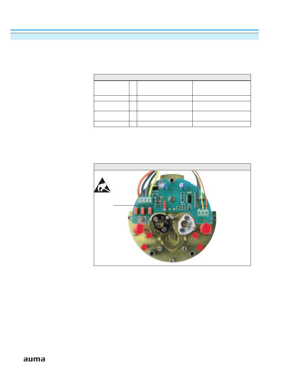
The position transmitter board (figure W) is located under the cover plate
(figure Y).
30
Multi-turn actuators SA 07.1 – SA 30.1/ SAR 07.1 – SAR 30.1
with actuator controls AUMA MATIC AM 01.1 / AM 02.1
Operation instructions
Terminal plans
KMS TP_ _ 4 / _ _ _
3- or 4- wire system
KMS TP _ 4 _ / _ _ _
KMS TP _ 5 _ / _ _ _
2-wire system
Output current
I
a
0 – 20 mA, 4 – 20 mA
4 – 20 mA
Power
supply
U
v
24 V DC, ±15 %
smoothed
14 V DC + (I x R
B
),
max. 30 V
Max. input
current
I
24 mA at 20 mA
output current
20 mA
Max. load
R
B
600
Ω
(Uv - 14 V) / 20 mA
Table 3: Technical data RWG 4020
Figure W: Position transmitter board
S1