8 positioner in split range version (option), 1 split range: description of functions, 2 programming – AUMA Electric multi-turn actuators SA 07.1 - 16.1_SAR 07.1 - 16.1 MATIC AM 01.1 - 02.1 User Manual
Page 47: 3 positioner adjustment for split range, Split range version 47
21.8 Positioner in Split Range version (option)
For Split Range, a modified version of the positioner is used. The standard ver-
sion is not suitable for Split Range operation.
Split Range operation is only possible with the position transmitter RWG.
21.8.1 Split Range: description of functions
In Split Range operation, a setpoint is shared by up to four positioners. A typical
example is a pipeline with a bypass. The actuator mounted on the bypass reacts
in the lower range (0 – 10 mA), the actuator on the main valve in the upper
range (10 – 20 mA). Other values such as 4 – 12 mA and 12 – 20 mA can also
be set.
21.8.2 Programming
DIP 5 at code switch S1-7 must always be in position ON for Split Range ver-
sion.
The further programming of the positioner via the code switch S2-7 can be
made in the same way as during normal operation.
21.8.3 Positioner adjustment for Split Range
(see also example further down the page)
.
Supply the specified minimum command signal (nominal value E1) for the
positioner and check by measuring with voltmeter at the measuring points MP3
and MP4 (figure AK).
.
Connect voltmeter between measuring point M3 and measuring point MP1.
Calculate setting value:
Initial value = E 1
min
[in Ampere] x 250 Ohm
Set initial value with potentiometer P5.
.
Supply specified maximum command signal (nominal value E1) and check by
measuring at the measuring points MP3 and MP4.
.
Connect voltmeter between measuring point M9 and measuring point MP1.
Set potentiometer P6 to 5 V.
.
Supply input signal E1 from minimum to maximum value and check the set
range 0 – 5 V at measuring point M9. If necessary, readjust with P5 or P6.
.
Apply the same procedure to the second actuator’s positioner and set accord-
ing to the specified nominal values E1.
.
After setting the Split Range operation, perform further readjustment as
described on page 41.
47
Multi-turn actuators SA 07.1 – SA 30.1/ SAR 07.1 – SAR 30.1
Operation instructions
with actuator controls AUMA MATIC AM 01.1 / AM 02.1
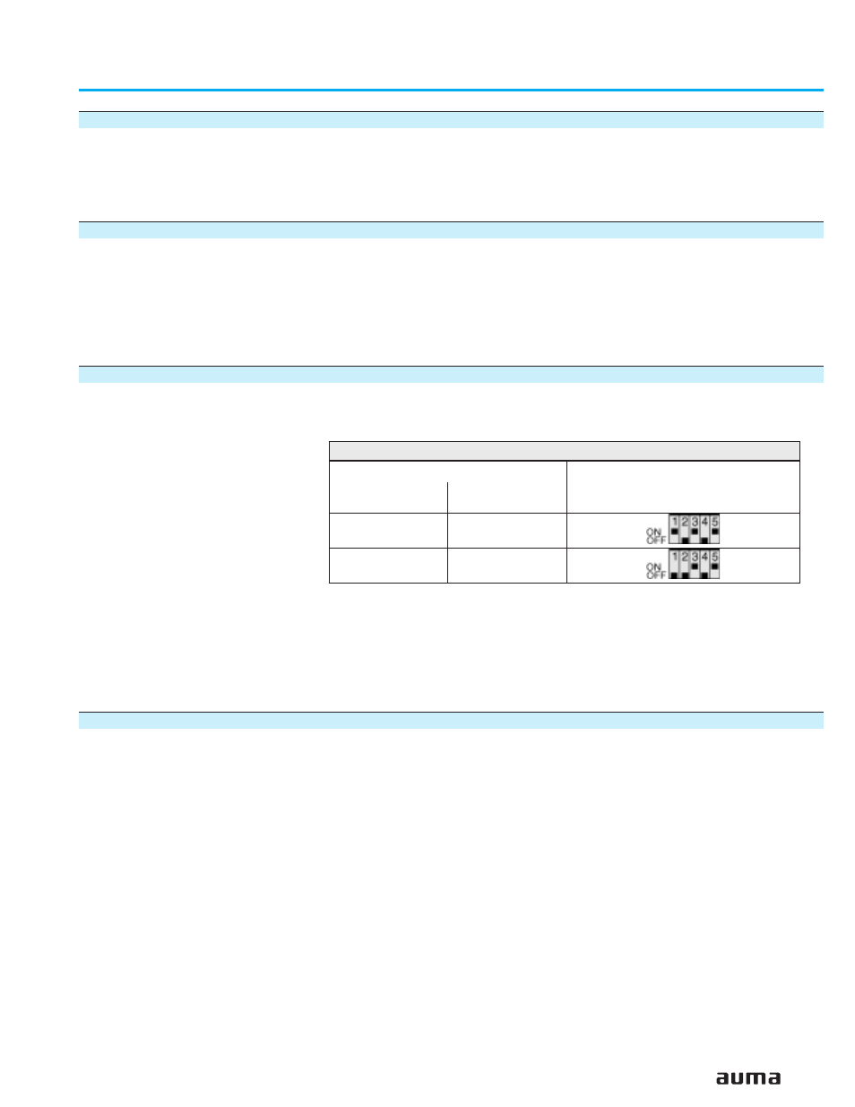
Programming
Command signal
Setpoint E1
Feedback
1)
Actual value E2
via DIP switch S1-7
(see figure AK)
4 – 12/12 – 20 mA
0 – 10/10 – 20 mA
4 – 20 mA
0 – 20 mA
4 – 12/12 – 20 mA
0 – 10/10 – 20 mA
0 – 5 V
1)
Signals for internal feedback:
0/4 – 20 mA from electronic position transmitter
Table 12: Possible settings for Split Range operation