Trigger and timebase characteristics (nom) – Atec Agilent-53200A Series User Manual
Page 9
9
53210A
53220A
53230A
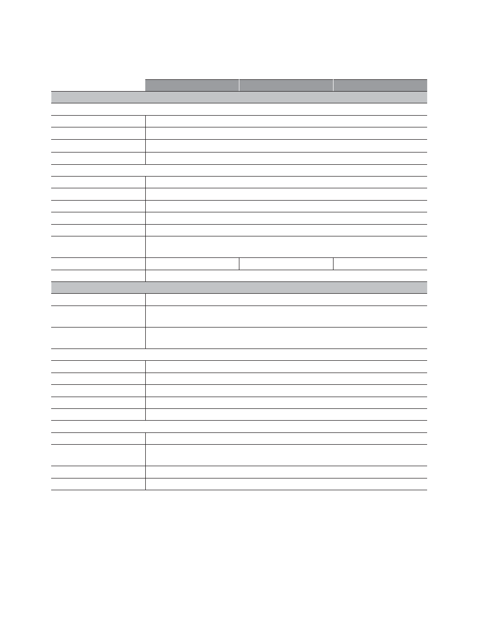
Trigger characteristics (nom)
General
Trigger source
Internal, external, bus, manual
Trigger count
1 to 1,000,000
Trigger delay
0 s to 3600 s in 1 µs steps
Samples/trigger
1 to 1,000,000
External trigger input (typ)
Connector
Rear panel BNC(f)
Impedance
1 kΩ
Level
TTL compatible
Slope
Selectable positive or negative
Pulse width
> 40 ns min.
Latency
2
Frequency, period: 1 µs + 3 periods
time interval, totalize: 100 ns
External trigger rate
300/s max
1 k/s max
10 k/s max
Damage level
<-5 V, >+10 V
Timebase characteristics (nom)
Timebase reference
Internal, external, or auto
Timebase adjustment
method
Closed-box electronic adjustment
Timebase adjustment
Resolution
10
-10
(10
-11
for Option 010 U-OCXO timebase)
External timebase input (typ)
Impedance
1 kΩ AC coupled
Level (typ)
100 mVrms to 2.5 Vrms
Lock frequencies
10 MHz, 5 MHz, 1 MHz
Lock range
±1 ppm (±0.1 ppm for Option 010 U-OCXO timebase)
Damage level
7 Vrms
Timebase output (typ)
Impedance
50 Ω ± 5% at 10 MHz
Level
0.5 Vrms into a 50 Ω load
1.0 Vrms into a 1 kΩ load
Signal
10 MHz sine wave
Damage level
7 Vrms
1. Continuous, gap-free measurements limits the Gate Time setting to 10 µs to 1000 s in 10 µs steps.
2. Latency does not include delays due to auto-leveling.
Trigger and Timebase Characteristics (nom)