Atec Agilent-34980A User Manual
Page 18
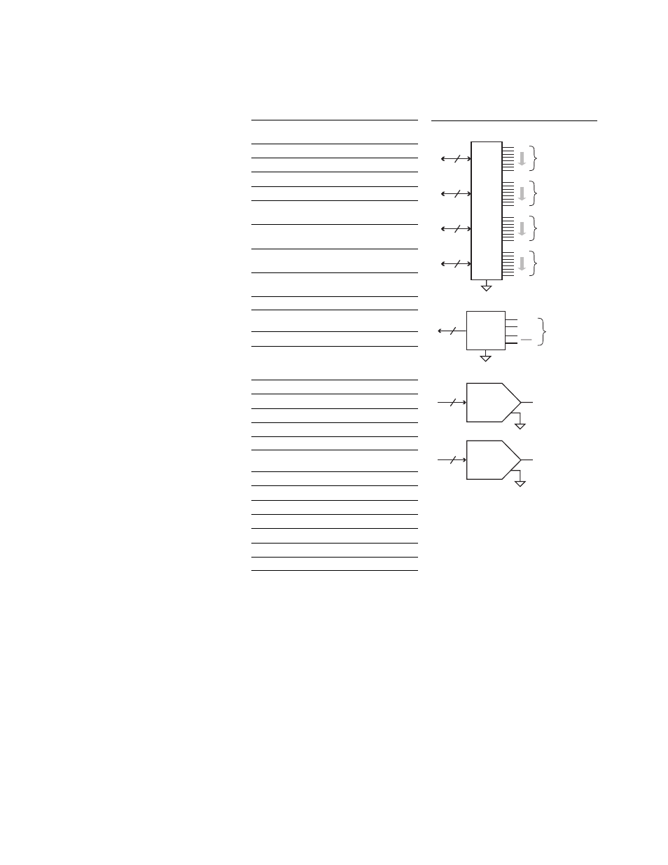
34952A multifunction module
with 32-bit DIO, 2-channel D/A
and totalizer
The multifunction module offers the
flexibility you need for system control.
The 34952A has four 8-bit digital I/O
channels, a 100-kHz gated totalizer,
and two ± 12 V analog outputs—all on
a single earth-referenced module. The
digital inputs and totalizer input may
be included in a scan list. Alarm limits
for the digital and totalizer inputs are
evaluated continuously, capturing
and logging alarm conditions even
between scans. Connections can be
made via standard 50-pin Dsub cables
or detachable terminal block.
Digital input/output characteristics
Four 8-bits channels, 8 bits wide, input or output,
non-isolated
Vin(L)
< 0.8 V (TTL)
Vin(H)
> 2.0 V (TTL)
Vout(L)
< 0.8 V @ Iout = -400 mA
Vout(H)
> 2.4 V @ Iout = 1 mA
Vout(H) max
< 42 V with external open
drain pull-up
Alarm
Maskable pattern match
or state change
Speed
4 ms (max) alarm sam-
pling
Latency
5 ms (typical) to 34980A
alarm output
Read/write speed
95/s
Totalize input characteristics
Max count
2
26
- 1
Totalize input
100 kHz (max) rising or
falling edge,
programmable
Signal level
1 Vp-p (min) 42 Vpk (max)
Threshold
0 V or TTL
Gate input
TTL-Hi, TTL-Lo, or none
Count reset
Manual or read + reset
Read speed
85 rds/s
Analog output characteristics
DAC 1, 2
± 12 V, non-isolated
Resolution
1 mV
IOUT
10 mA max
Settling time
1 ms to 0.01% of output
Accuracy
± (% of output + mV)
1 year
± 5°C 0.25% + 20 mV
Temp. coefficient
± (0.015% + 1mV)/°C
18
Channel
06
Channel
05
16 Bits
16 Bits
Cnt H
Cnt L
Gate
Gate
DAC
1
Totalizer
Channel
07
16 Bits
DAC
2
Channel
04
8
Bit0
Bit7
DIO
bank
Channel
03
8
Bit0
Bit7
Channel
02
8
Bit0
Bit7
Channel
01
8
Bit0
Bit7
Figure 12. 34952A multifunction module