Atec Agilent-34980A User Manual
Page 17
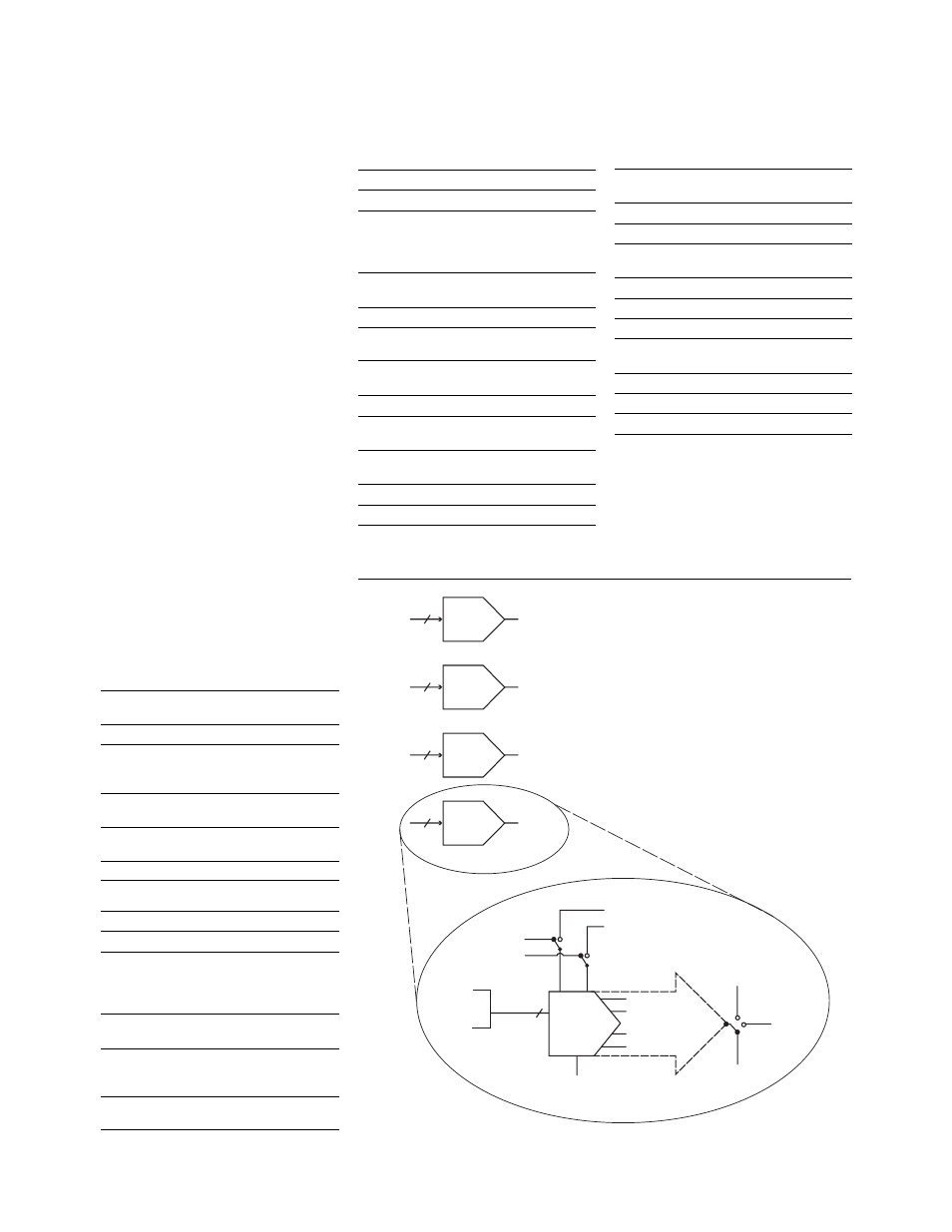
34951A 4-channel isolated
D/A converter with wave-
form memory
This module has four independent,
isolated channels that output DC
voltage up to ± 16 V or DC current up
to ± 20 mA. The gain and offset can
be adjusted on-the-fly. Each channel
can be controlled manually, or use
the onboard memory to download a
waveform. These waveforms can be
dynamically allocated among one or
more channels and output as a point-
to-point arbitrary waveform generator
at up to 200k points/sec. You can use
the standard sine, square or ramp
wave shapes provided or define your
own wave shape using over 500,000
points and output to a device under
test.
The calibration command connects
the D/A converters to the internal
DMM to be automatically calibrated.
Connections to the module can be
made via standard 50-pin Dsub cables
or a detachable terminal block.
General specifications
Maximum update
rate:
200 kHz point-to-point
Monotonic :
to 16-bits
Isolation:
> 80 VDC/AC peak
(chan-to-chassis or
chan-to-chan)
Synchronization:
Software commands or
external trigger
Internal/external
CLK accuracy:
100 ppm
AC accuracy:
Not specified
DC voltage
Amplitude:
± 16 V up to 10 mA
Resolution:
16-bits = 500 uV
Amplitude
accuracy (DC):
± (0.05% + 3.0 mV
(90 days, Tcal ± 5°C or
*Cal? ± 5°C)
Ripple and noise:
< 2 mVrms, 20 Hz to
250 kHz into 10 k
Ω load
Settling time:
40 uS (-full scale to +full
scale step, single channel,
to rated accuracy)
Output impedance:
< 1
Ω with the load
sensed
DC current
Range:
± 20 mA
Resolution:
16-bit = 630 nA
Accuracy:
± (% value + amps)
(temperature within ± 5°C
of Tcal or *Cal?) 90-day:
± (0.09% + 5.0 uA)
Ripple and noise:
< 2 uArms, 20 Hz to
250 kHz into 250
Ω
Compliance voltage:
± 12 V
Max open circuit
voltage: <
± 22
V
Phase-locking I/O trigger characteristics
Trigger input
Input level:
TTL compatible
(3.3 V logic, 5 V tolerant)
Slope:
Rising or falling,
selectable
Pulse width:
> 100 nS
Input impedance:
> 10 k
Ω, DC coupled
Trigger output
Level:
TTL compatible
into 1 k
Ω (3.3 V logic)
Output impedance:
50
Ω typical
Clock input
Input level:
TTL compatible
(3.3 V logic, 5 V tolerant)
Input impedance:
> 10 k
Ω, DC
Maximum rate:
10 MHz
Clock output
Level:
TTL compatible
into 1k
Ω (3.3 V logic)
Output impedance:
50
Ω typical
Maximum rate:
10 MHz
Accuracy:
± 100 ppm
17
Channel
01
16 Bits
DAC 1
16 Bits
DACx
Channel
02
16 Bits
DAC 2
Channel
03
16 Bits
DAC 3
Channel
04
Internal clock
Internal trigger
User supplied clock (bidirectional)
User supplied trigger (bidirectional)
HI voltage sense
Disconnect
Calibration bus
(ABUS 1)
Customer
system
HI
LO
LO voltage sense
Immediate
data
Calibration constant
in non-volatile memory
Waveform
memory
16 Bits
DAC 4
Figure 11. 34951A 4-channel isolated D/A converter