Atec Agilent-34980A User Manual
Page 12
34980A general-purpose switch
modules
The 34980A general-purpose switches
can be used to route signals or to
control other system devices. These
switches are ideal for device actua-
tion and switching loads or power
supplies.
Choose from the following features:
• Form C channels up to 1 A, 50 W
• Form A channels up to 5 A, 150 W
• Armature latching relays
• Simultaneous channel switching
• Temperature sensor to detect
overheating conditions
• Connections via standard 50-pin
Dsub cables or detachable terminal
block
The 34937A is the most versatile
general-purpose switch with 28 Form C
channels that can switch up to 1 A of
current. In addition, this module has
four Form A channels that can switch
up to 5A of current. For power
switching applications, the 34938A
has 20 5-amp channels in a Form A
topology. Each Form A general-purpose
switch can handle up to 150 W, enough
for many power line-switching
applications.
The 34937A and 34938A contain
latching armature relays where
multiple channels can be closed at the
same time. Additionally, for switching
reactive loads, the optional terminal
blocks have pads for snubbing circuits.
The built-in relay counter helps pre-
dict when relays need to be replaced.
12
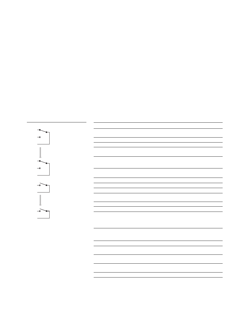
Channel 001
(1A form C relay)
NC
NO
COM
Channel 028
(1A form C relay)
NC
NO
COM
Channel 029
(5A form A relay)
NO
COM
Channel 032
(5A form A relay)
NO
COM
Table 4. GP actuator selection table—specifications and characteristics*
34937A
34938A
Channels/configurations
28 Form C
20 Form A
4 Form A
Switch type
Armature, latching
Armature, latching
Input characteristics (per channel)
Max volts (DC, AC RMS)
[1]
Form C – 300 V
30 VDC/250 VAC
Form A – 30 VDC/250 VAC
Max current (DC, AC RMS)
Form C – 1 A (2 A carry)
5 A switch
Form A – 5 A switch
(8 A carry)
(8 A carry)
Power (W, VA)
[2]
Form C – 60 W
Form A – 150 W
150 W
Volt-Hertz limit
10
8
10
8
General specifications
Offset voltage
3 uV
3 uV
Initial closed channel res
Form C – 125 m
Ω
Form A – 50 m
Ω
< 60 m
Ω
AC characteristics
Bandwidth at terminal block
[3]
10 MHz
1 MHz
Channel Isolation at terminal block
[3]
100 kHz
55 dB
60 dB
1 MHz
35 dB
40 dB
10 MHz
15 dB
Capacitance at terminal block
CH – CH
Form C 12 pF/ Form A 10 pF
65 pF
CH – earth
Form C 21 pF/Form A 18 pF
105 pF
General characteristics
Relay life no load/rated
Form C – 100 M/100 k
Form A – 50 M/30 k
50 M/30 k
Open/close time
Form C – 4 ms/4 ms
10 ms/10 ms
Form A – 10 ms/10 ms
Initial/reset relay state
Form C – maintain state
user configurable
Form A – user configurable
Analog bus backplane connection
No
No
[1] DC or AC RMS voltage, channel-to-channel or channel-to-earth
[2] Limited to 6 W of channel resistance power loss per module
[3] 50
Ω source, 50 Ω load, differential measurements verified (S21)
* See User’s Guide for additional specifications
Figure 6. 34937A 32-channel Form A/
Form C switch