Atec Acterna-JDSU-ANT-20SE User Manual
Page 8
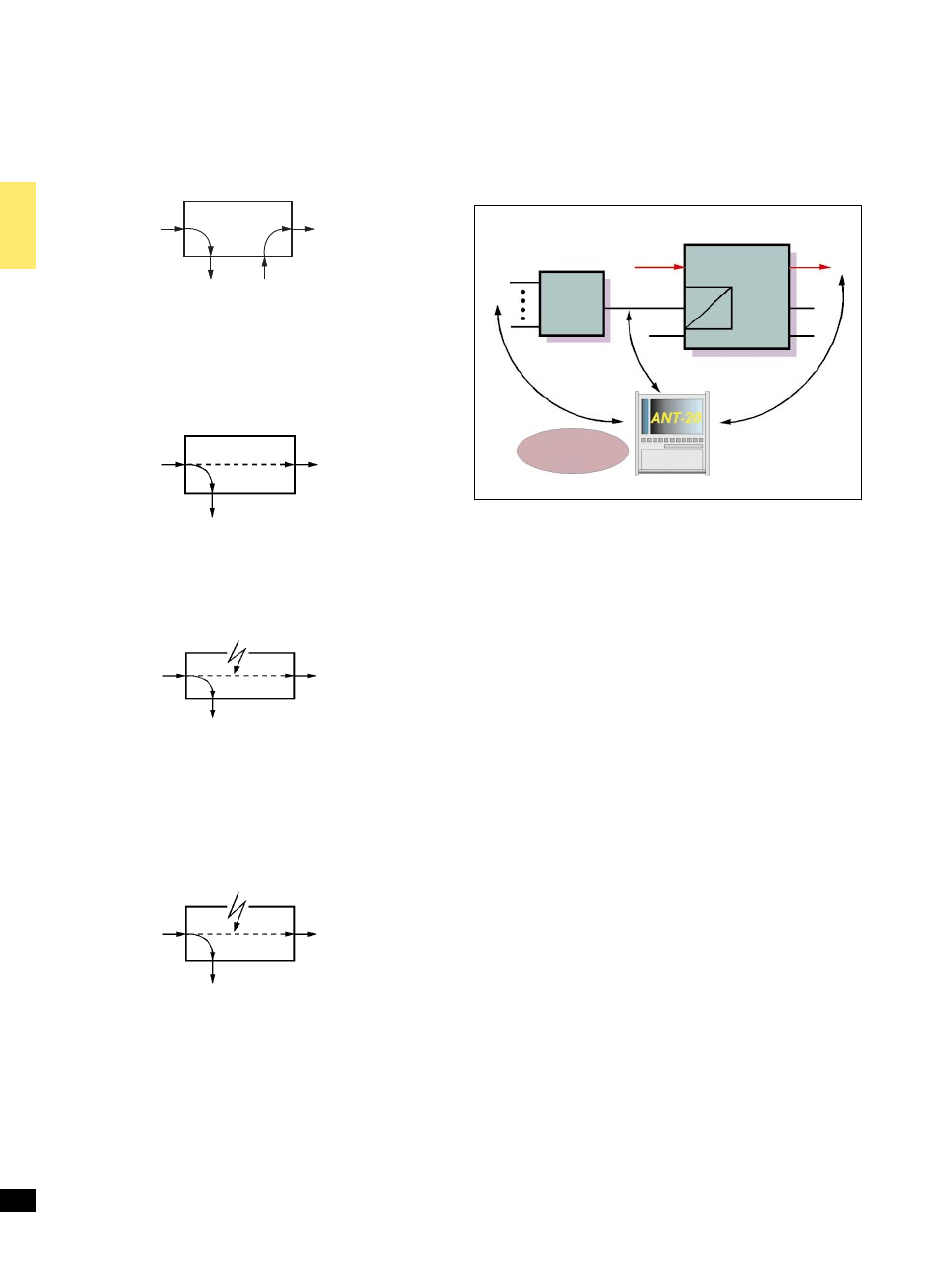
Figure 6: Testing hybrid systems with M13 MUX/DEMUX.
Drop & Insert
BN 3060/90.10
This option provides the following functions:
1. Generator and receiver operate independently
as mapper and demapper. The DS1/DS3 signal from a selected
channel is dropped from the receive signal and output to a
connector. An external or internal DS1/DS3 signal is inserted into
the transmit signal.
2. Through mode:
The received signal is looped through the ANT-20SE and re-
transmitted (generator and receiver coupled). The DS1/DS3 signal
from a selected channel may be dropped from the receive signal and
output to a connector. An internal DS1/DS3 signal may be inserted
into the transmit signal. The ANT-20SE can operate here as an active
signal monitor without affecting the signal.
3. Through mode jittering:
The looped-through DS1/DS3 or SONET signal can also be jittered
using the Jitter Generator option. This applies to all jitter
frequencies up to 622 Mbit/s depending on the jitter option fitted.
4. Error insertion in through mode:
The looped-through synchronous signal can be manipulated if
required:
± Overwriting bytes in the TOH
(except B1, B2, H1 to H3)
± Anomaly insertion
± Defect generation by programming the TOH
5. Block and Replace (B & R)
For this function, the ANT-20SE is looped into the working fiber of
a ring. B&R allows replacement of a synchronous tributary (e.g.
STS-1 including TOH, POH and payload) in a OC-N signal. This
can then be measured by the ANT-20SE from the ring. By inserting
specific errors, the error thresholds of the APS mechanism in the
system can be tested.
Additional input and output for tributary signals
75 O, coaxial BNC; line codes as for mainframe instrument
Input and output for balanced tributary signals: Use balanced
connectors on mainframe
M13 MUX/DEMUX chain
BN 3060/90.12
M13 multiplexers are used in North America in hybrid networks and
synchronous system cross-connects. This option provides n6DS0 to
DS3 multiplex and demultiplex functions. The output signal is fed to
the electrical interface and is available as payload in mappings
(requires options BN 3060/90.02 or BN 3060/90.04).
Alarms and errors can be generated and analyzed.
64k/140M MUX/DEMUX chain BN 3060/90.11
This option provides n664 kbit/s to 140 Mbit/s multiplex and
demultiplex functions. The output signal is fed to the electrical inter-
face (requires option BN 3060/90.04) and is available as payload in
mappings (requires option BN 3060/90.04).
Alarms and errors can be generated and analyzed.
8
Asynchronous tributary
OC-M/STM-N
e/o
OC-M/STM-N
e/o
Asynchronous tributary
OC-M/STM-N
e/o
OC-M/STM-N
e/o
OC-M/STM-N
e/o
Asynchronous tributary
OC-M/STM-N
e/o
Jitter
Asynchronous tributary
OC-M/STM-N
e/o
Error/Alarm
OC-M/STM-N
e/o
Cross connect
DS1,
VT1.5
DS3
DS1
OC-N
W-DCS
OC-N
DS1
OC-N
Built-in
M13 MUX/DEMUX
DS1
DS1
DS3
MUX
M13
DS3/DS1
DS1