Atm options – Atec Acterna-JDSU-ANT-20SE User Manual
Page 19
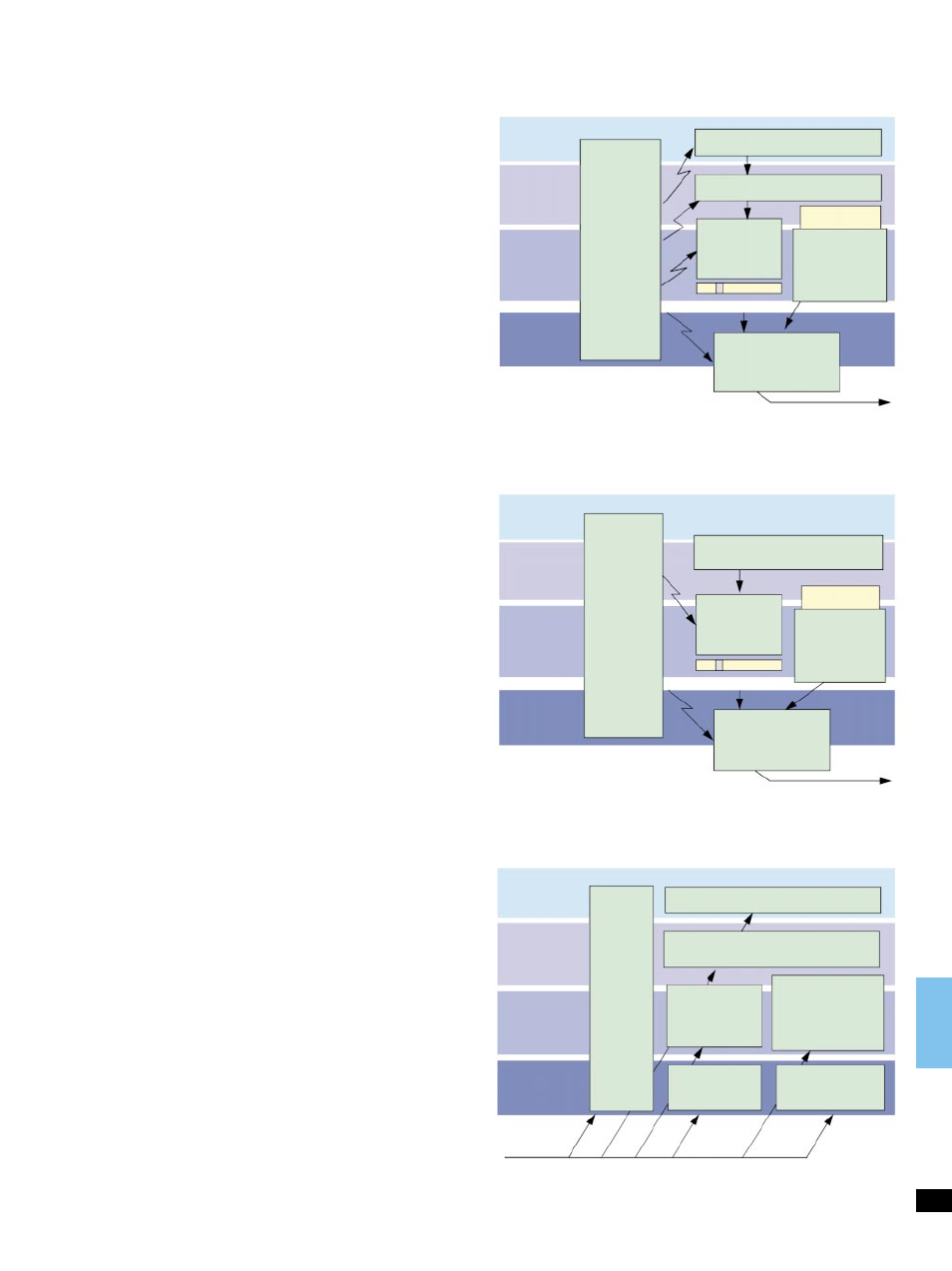
Service
Layer
ATM
Adaptation
Layer
ATM
Layer
Physical
Layer
Anomaly
and
Defect
Insertion
PRBS Generator
Test Cell
Channel
Cell Editor
Background
Load
Generator
Load, profile
Test signal
AAL-1, AAL-0 Mapper
Framing
Generator
SDH/PDH/SONET
Figure 14:
ATM-BERT generator configuration.
Service
Layer
ATM
Adaptation
Layer
ATM
Layer
Physical
Layer
Anomaly
and
Defect
Insertion
Test Cell
Channel
Cell Editor
Background
Load
Generator
Load, profile
Test signal
O.191 Test Information
Framing
Generator
SDH/PDH/SONET
Figure 15: Generator configuration
for performance measurement.
Service
Layer
ATM
Adaptation
Layer
ATM
Layer
Physical
Layer
Anomaly
and
Defect
Analyzer
ATM BERT, QoS
AAL-1 Circuit-Reassembly
AAL-1 Performance
ATM
Performance
I.356
Traffic Channel
Analysis and
Load
Measurement
Pointer-
Analyzer
SOH/POH
Monitor
Test signal
Figure 16: Analyzers in the ANT-20SE ± A hierarchical overview.
ATM Options
ATM Basic
BN 3060/90.50
General
Adjustable test channel from 0 to 150 Mbit/s
In ATM network elements, user channels are monitored with the UPC
(usage parameter control). The sensors of the control instance can be
quickly checked if the bandwidth of a test channel exceeds the set
threshold in the network element. For all measurements, the test
channel in the ANT-20SE is set on-line. Settings are made directly with
a control (Figure 15) which shows the bandwidth in Mbit/s, Cells/s or
%. This makes it easy to simulate CBR (Constant Bit Rate) sources.
For each interface, the load setting has a range from 0.01 % to 100 %.
This corresponds to the load conditions which can occur in the real
world.
Load profiles
A test channel can be generated with typical load profiles in order to
stress network elements or simulate source profiles. In burst mode, for
example, the burst load, burst length and burst period parameters can
be used to simulate a video signal whose key figures correspond to a
real-life signal.
Background load generator
To make a real-time measurement under loaded conditions, additional
background load can be simulated to supplement the test channel
(foreground traffic). The ATM channels are defined using an editor.
The user specifies the repetition rate of the load cell and a sequence of
empty cells. Load channels can be transmitted continuously as a
sequence. The load generator can also be used separately with the test
channel switched off. In this case, the channels and profiles can be
user-specified.
Determining Cell Delay Variation
The ANT-20SE includes very powerful tools for measuring delay
parameters. Once a precise measurement has been made, subsequent
measurements usually require only a low-resolution display to allow
rapid pass/fail assessment. Delay values are displayed by the ATM
Traffic Analyzer as a histogram with a minimum class width equal to
160 ns (maximum 335 ms).
As a result, delay fluctuations are shown graphically with the same
resolution. An adjustable offset can be used to maintain measurement
accuracy even if the delay values are high, e.g. over international links.
F4/F5 OAM alarm flow
In accordance with I.610 and the ATM forum standard, the status of
ATM paths and channels is transmitted in the OAM cell stream (fault
management). The ANT-20SE generates the alarms VP-AIS, VC-AIS
or VP-RDI, VC-RDI for the foreground channel. The receiver
simultaneously detects alarms and error messages in the channel
and path.
19