Alpha Technologies Cordex CXCRF 48-300W User Manual
Page 30
0300072-J0 RevA
Page 26 of 46
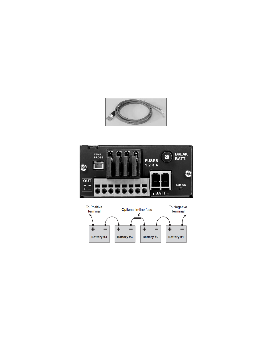
5. Verify the battery connector polarity and DC voltage with a DC voltmeter. If correct, plug it into the battery
connector at the front of the distribution unit (Figure 25).
6. Route the sensor end of the battery temperature cable to the batteries. Tape it to the side
of the centre of the batteries string. As the cable terminal is voltage free, the sensor can even be placed
directly on one of the copper bar inter-cell links. Insert the temperature sensor connector into the battery
temperature probe socket at the front of the distribution unit (Figure 24 & Figure 25).
7. To activate the battery, push (close) the battery circuit breaker at the distribution unit and ensure that the
LVD is closed (“LVD OK” LED is on) (see Figure 25).
As batteries can be charged and discharged by the 48-300W Modular Switched Mode Rectifier System, the DC
bus voltage and the charging current have to be defined by the MCU. The factory voltage has been set to -54.0
V at +25°C and the charging current has no limitation. When the temperature sensor is connected and activated,
the temperature compensation is -3mV/K/cell. The battery disconnection voltage is fixed at 43.2V (1.8V per cell).
Figure 24 : Battery temperature sensor NTC @10kΩ at +25°C (NTC 10K B=3977K)
Figure 25 : Battery connections