2 usb port, 3 ethernet port, 4 battery test save – Alpha Technologies Cordex CXCRF 48-300W User Manual
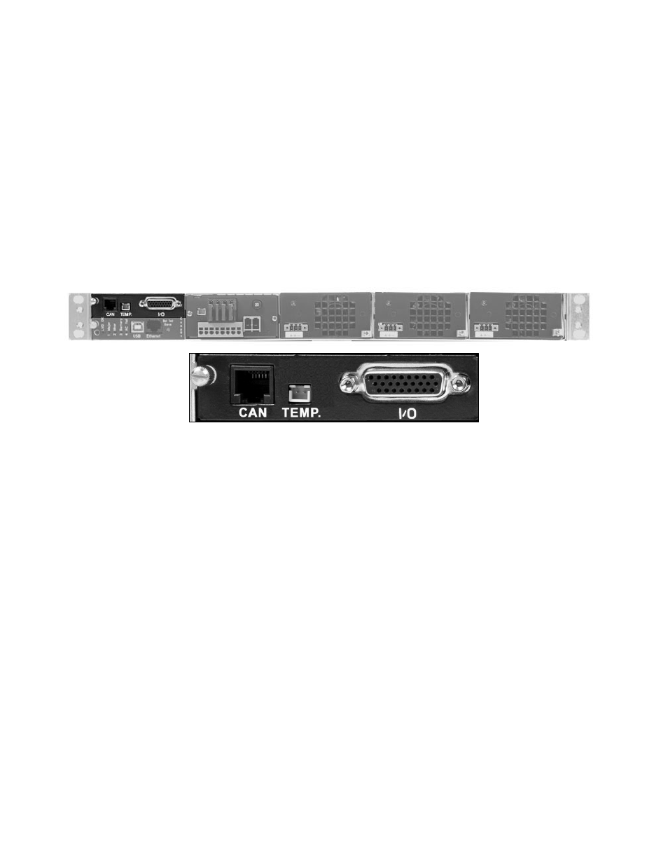
Page 13: 2 front signal connection card, 1 can port, 2 temperature sensor connection (environmental), 3 signals in/out, Front signal connection card
0300072-J0 RevA
Page 9 of 46
•
3 Battery alarm
Red LED indicates a battery failure
•
4 AC fail alarm
Red LED indicates a mains failure
2.6.1.2 USB
PORT
The USB port is designed for connecting a computer to the system controller via a standard USB cable (type
A/B), with direct access to the Comp@s software (Comp@s card required).
2.6.1.3 E
THERNET PORT
The Ethernet port is designed for connecting the controller to a user supplied network (TCP/IP secured by the
user) via an RJ-45 jack and a standard network cable.
2.6.1.4 B
ATTERY TEST SAVE
This button can be used for starting a battery test (see section 4.4.3 for more information).
2.6.2 Front signal connection card
Figure 5 : Front signal connection card
The front signal connection card (optional) is located just above the low profile MCU. It provides a front access
point for communication of different signals:
2.6.2.1 CAN
PORT
This CAN port enables the connection of the CDM Comp@s display module (RJ-45 inverted 8P8C).
2.6.2.2 T
EMPERATURE
S
ENSOR CONNECTION
(E
NVIRONMENTAL
)
The system enables the monitoring of the cabinet temperature via this connection point.
2.6.2.3 S
IGNALS
IN/OUT
The Sub-D 26-pole connector allows the user to monitor the system via the potential free alarm relays.
In addition the user has four digital inputs, which can be monitored by the MCU.
•
4 digital inputs (e.g., door contact open)
•
4 alarm outputs (relay contacts can be programmed individually with single alarm or a combination of
alarms)