Alpha Technologies Cordex CXCRF 48-300W User Manual
Page 24
0300072-J0 RevA
Page 20 of 46
Signals
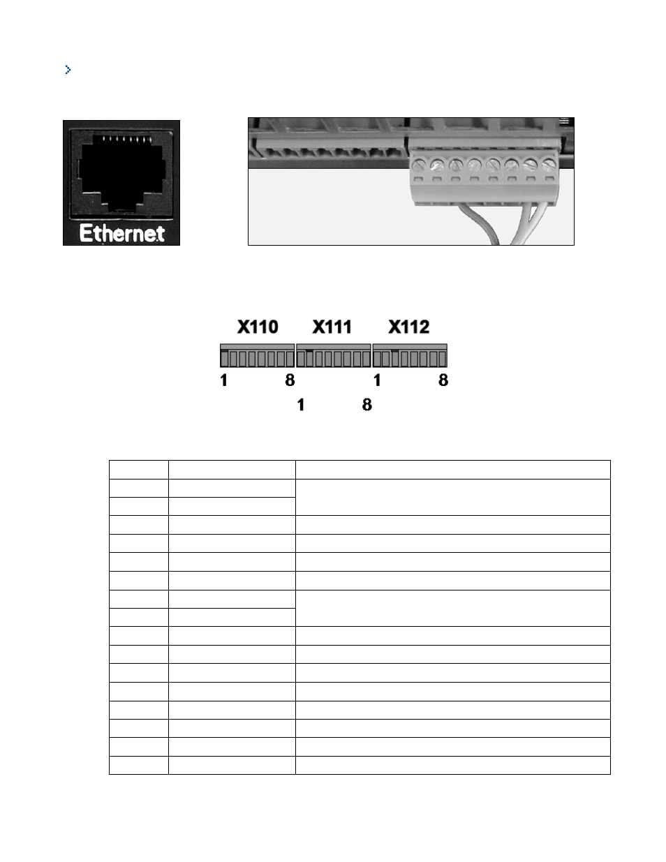
If used, make the Ethernet connection via the port on the front of the controller (Figure 14) and signal connectors
at the rear of the shelf (Figure 15)
Figure 14 : Front ethernet port
Figure 15 : Rear signal connectors
Optionally, a set of mating connectors can be provided with the system.
Figure 16 : Signal connector pinning
The following table lists all the pin assignments for the signal connectors:
X110
Name
Remarks
1
--
DO NOT CONNECT
2
--
3
0 V signal
0V signal for Temp. sensor and the four digital inputs
4
Tenv. sensor
Thermal sensor (NTC 10kΩ) with 0V signal
5
DIG_IN1
External digital input 1 – used with 0V signal
6
DIG_IN2
External digital input 2 – used with 0V signal
7
CANH
CAN bus
8
CANL
X111
Name
Remarks
1
DIG_IN3
External digital input 3 – used with 0V signal
2
DIG_IN4
External digital input 4 – used with 0V signal
3
Dig_Out1_common
Common point of potential free alarm 1
4
Dig_Out1_n_open
Normally open contact of potential free alarm 1
5
Dig_Out1_n_closed
Normally closed contact of potential free alarm 1
6
Dig_Out2_common
Common point of potential free alarm 2
7
Dig_Out2_n_open
Normally open contact of potential free alarm 2