Alpha Technologies Cordex CXCRF 48-300W User Manual
Page 26
0300072-J0 RevA
Page 22 of 46
X104
Name
Remarks
17
Dig_Out2_common
Common point of potential free alarm 2
18
Dig_Out1_common
Common point of potential free alarm 1
19
--
DO NOT CONNECT
20
--
21
--
22
--
23
Dig_Out4_n_closed
Normally closed contact of potential free alarm 4
24
Dig_Out3_n_closed
Normally closed contact of potential free alarm 3
25
Dig_Out2_n_closed
Normally closed contact of potential free alarm 2
26
Dig_Out1_n_closed
Normally closed contact of potential free alarm 1
Table 2 : Sub-D26 signal connector pin assignments
DC Output
There are 3 different load connection options with the 48-300W Modular Switched Mode Rectifier System:
1. Output terminal block of the distribution unit (only for stand-alone systems) (Figure 19)
2. DC bus at rear of the shelf (Figure 20)
3. Auxiliary DC output (300W max.) on the front of each rectifier (Figure 21)
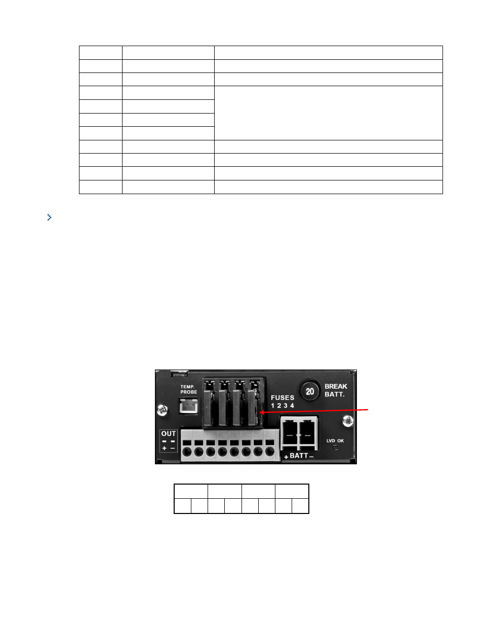
1. Terminal block with four protected DC outputs:
The rectifiers are connected in parallel:
•
If the fuse box is empty, insert a alarm-indicating fuse (2A or 5A or 10A) in the fuse holder of the
distribution unit.
•
Insert wires (stripping length 10mm) in the associated position in the spring cage terminal block. A flat
screwdriver can be used to assist in the insertion or removal of these wires.
Figure 19 : Front terminal block DC outputs
Out 1
Out 2
Out 3
Out 4
+
-
+
-
+
-
+
-
2. DC Bus at rear side:
A load can be connected directly to the DC bus by making connections to the screw-type connector (M5
inserts), as shown in Figure 20.
Alarm indicating
fuse