Alpha Technologies Cordex CXCRF 48-300W User Manual
Page 25
0300072-J0 RevA
Page 21 of 46
8
Dig_Out2_n_closed
Normally closed contact of potential free alarm 2
X112
Name
Remarks
1
Dig_Out3_common
Common point of potential free alarm 3
2
Dig_Out3_n_open
Normally open contact of potential free alarm 3
3
Dig_Out3_n_closed
Normally closed contact of potential free alarm 3
4
Dig_Out4_common
Common point of potential free alarm 4
5
Dig_Out4_n_open
Normally open contact of potential free alarm 4
6
Dig_Out4_n_closed
Normally closed contact of potential free alarm 4
7
--
DO NOT CONNECT
8
--
Table 1 : Signal connector pin assignments
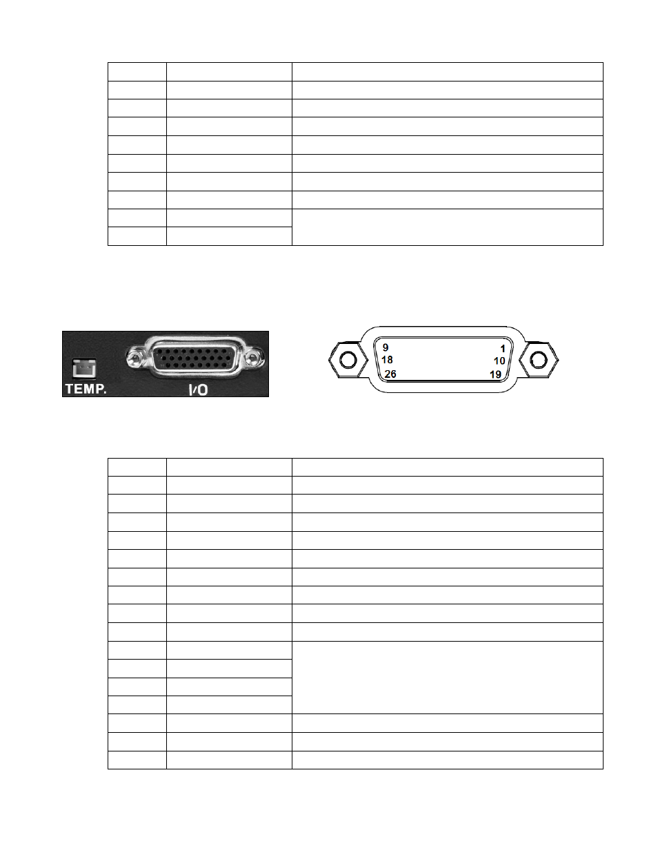
Signal connections can be brought back to the front of the shelf via the front signal connection card
Figure 17 : Front signal connectors
Figure 18 : Sub-D 26 poles pin layout
The following table lists all of the pin assignments for the Sub-D26 signal connector:
X104
Name
Remarks
1
DIG_IN4
External digital input 4 – used with 0V signal
2
DIG_IN3
External digital input 3 – used with 0V signal
3
DIG_IN2
External digital input 2 – used with 0V signal
4
DIG_IN1
External digital input 1 – used with 0V signal
5
--
DO NOT CONNECT
6
Dig_Out4_n_open
Normally open contact of potential free alarm 4
7
Dig_Out3_n_open
Normally open contact of potential free alarm 3
8
Dig_Out2_n_open
Normally open contact of potential free alarm 2
9
Dig_Out1_n_open
Normally open contact of potential free alarm 1
10
0 V signal
0V signal
11
0 V signal
12
0 V signal
13
0 V signal
14
--
DO NOT CONNECT
15
Dig_Out4_common
Common point of potential free alarm 4
16
Dig_Out3_common
Common point of potential free alarm 3