5 overview of control unit configurations, 1 basic units, 6 features – Alpha Technologies Cordex CXCRF 48-300W User Manual
Page 12: 1 leds, Overview of control unit configurations, Basic units, Features
0300072-J0 RevA
Page 8 of 46
2.5 Overview of Control Unit Configurations
2.5.1 Basic units
MCU0348M4: Monitoring and control unit with LCD display.
Unit features USB and Ethernet port connectors for the communication card.
Display indications: output voltage, rectifiers and battery current.
Comp@s: Remote communication card with basic package.
OR
MCU0348M4LP: Monitoring and control unit for the energy system without LCD display. Unit features USB and
Ethernet port connectors for the communication card.
Front signal connection card (optional): Front access communication I/O card for digital inputs, alarm signals,
temperature sensor and CAN Bus.
Comp@s: Remote communication card with basic package.
2.6 Features
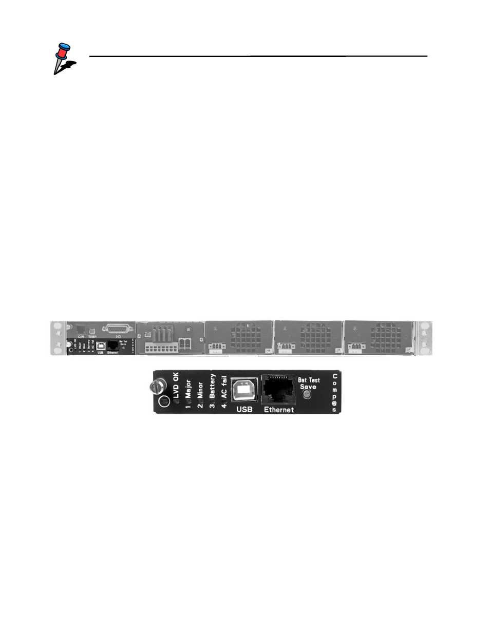
2.6.1 System controller (low profile MCU without LCD screen)
Figure 4 : System controller LED’s
2.6.1.1 LED
S
The monitoring unit has six LEDs located on the front panel. These are used to display the status of the
controller, LVD, system and battery:
•
Controller status Green LED indicates MCU and Comp@s functions are OK.
Green LED is blinking if no Comp@s is present.
•
LVD OK
Green LED indicates LVD (low voltage disconnection) is closed.
The green LED blinks during a battery test.
If the LED remains OFF, it means the LVD is open.
•
1 Major alarm
Red LED indicates a major alarm in the system (defined in the alarm table)
•
2 Minor alarm
Red LED indicates a minor alarm in the system (defined in the alarm table)
NOTE:
IEC C16 is a high temperature inlet which requires IEC C15 plug
IEC input voltage limitations are shown in section 2.4