4 replacing the internal batteries (continued), Step 2: charger voltage test, Procedure: 1 – Alpha Technologies CFR 3000, CFR 3000RM User Manual
Page 70: Charger voltage test finished
5
Maintenance
64
5.4
Replacing the Internal Batteries (Continued)
Step 2: Charger Voltage Test
This tests the unit’s charger so the new batteries will not damaged by a faulty charger. Do
this before removing the batteries.
Procedure:
1
Make sure:
• The Battery circuit breaker is switched off.
• The Input circuit breaker is switched on.
• The utility line is connected.
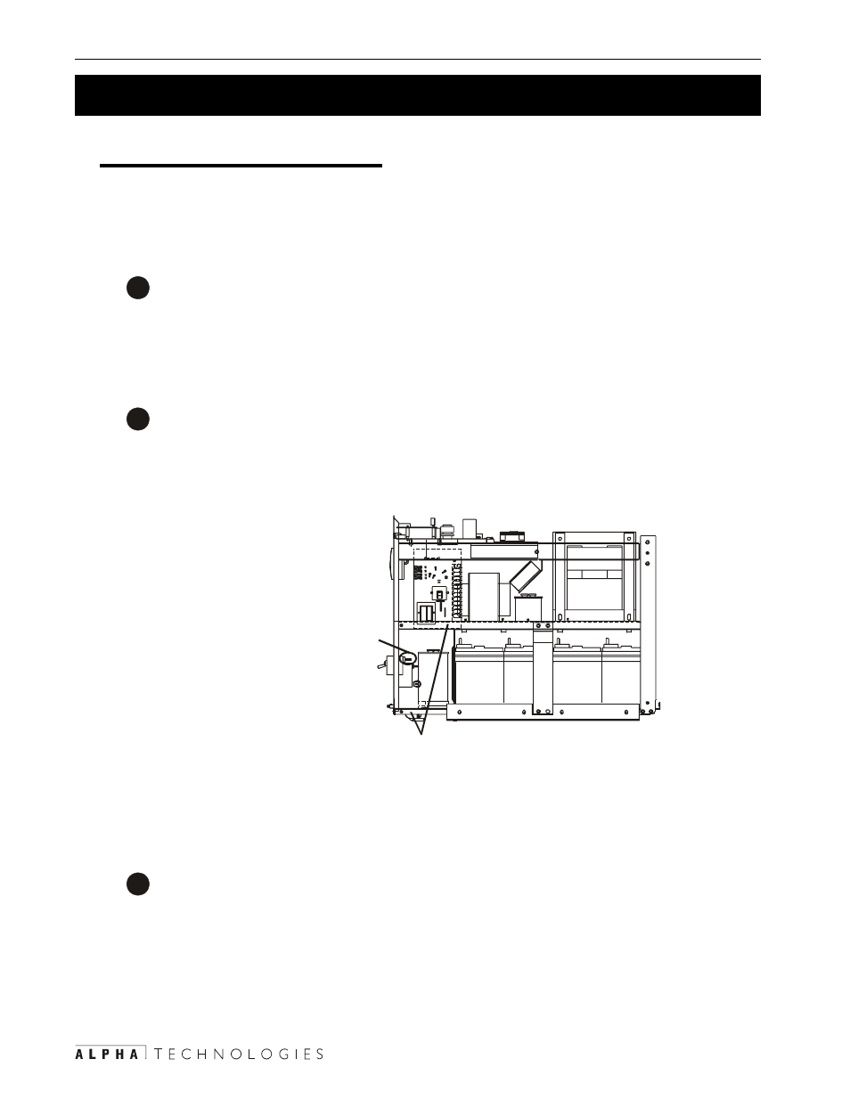
2
Measure the DC voltage by:
• Connecting the positive (+) to the top connector of the battery circuit breaker.
• Connecting the negative (–) to the chassis (Figure 5.2).
3
The voltage should be between 54 VDC to 57 VDC.
• If it is, switch off the Input circuit breaker, disconnect the utility line and go to Step 3.
• If it is not, the charger is faulty. Contact Alpha Technologies customer service de-
partment.
Charger Voltage Test Finished
Figure 5.2
Charger Voltage Test
W T 10 2
TO
O
U
TP
U
T
R
EC
EP
W T 10 3
2
1
D
2
1
Positive (+) to top connector of
BATTERY CIRCUIT BREAKER.
Negative (-) to unit chassis.
Voltage to be between
54 VDC to 57 VDC.