Probe, Installation – Franklin Fueling Systems Probe Installation Quick Reference User Manual
Page 2
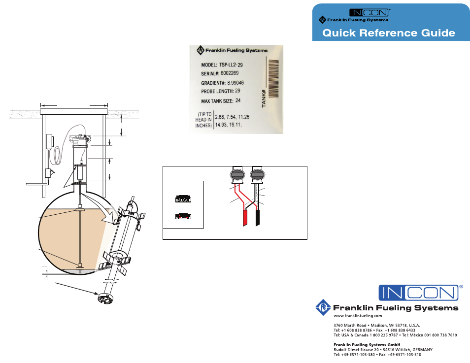
Record Probe Information
Probe information is needed when programming the tank
gauge. Find the information label included in the probe
splice kit and record which tank the probe is installed in.
Provide this to the person programming the tank gauge.
Sample Probe Information Label
LL2 Probe Splice Kit – Installation Instructions
The Liquid Level Probe Splice Kit includes 2 Electrical
Connectors for installation inside the manhole Junction Box.*
After Crimp
To
Console
To
Probe
Before Crimp
End view of splice
Black wire of probe
Both shield wires
Red wire of
field cable
Black wire of
field cable
Red wire
of probe
Connect bare metal shielding together
Splice Kit for Probe Wiring
1. Insert 2 red unstripped wires into two separate
openings of the first connector.
2. Insert 2 black unstripped wires into two separate
openings of the second connector and then insert
the 2 shield wires into the remaining opening of the
second connector.
3. Squeeze each connector together using 8” slip-joint pliers.
4. The white wire inside yellow probe cable is not
used. Cut the white wire back flush to the jacket
of the yellow probe cable.
* Refer to manual 000-1041, Direct Burial Cable Installation
Instructions and 000-1133, Direct Burial Splice Kit Installation
Guide, for information about direct-burial applications.
©2010 FFS 000-1166 Rev. A
Probe
Installation
Mounting Bottom-Mount Probes
Inventory probes come with hardware that allows them
to be installed resting on the bottom of the tank. This
hardware includes an extra spacer for the probe head
and a ¼" tall foot for the end of the shaft.
When using a 2" riser you will remove the top spacer
and replace the bottom spacer with the 2" spacer
included with the 2" floats. When using a 3" riser, break
off tabs on the top spacer and replace the bottom
spacer. No modification is needed for the 4" risers.
This is solely for the Inventory control probes, all leak
detection probes MUST BE suspended.
PRODUCT
Ullage
Probe end held
1/4" (6.4 mm) Above
Bottom of Tank
Water Float
Product
Float
6.0" (152 mm) Minimum
14" (356 mm) Minimum
Manhole Cover
8.0" (203 mm)
Reference
3" (76 mm)
Minimum
N.T.S.
Spacers
Bottom-Mount Probe Installation
(Inventory Probes Only)
Density Float
The product float and density float are matched and must
be purchased as a set.
Refer to manual 000-0527, Density Measurement Option
Installation Guide, for information about installing and
programming density floats.
Tank Gauge Setup
Refer to manual 000-2142, Fuel Management System
Programming Guide and 000-2150 Fuel Management
System Installation Guide for information about setting
up the probe with the tank gauge with the TS-5 series
consoles.
For Colibri Tank Gauge Consoles, refer to manual
000-2153, Colibri Automatic tank Gauge Installation
Guide, and 000-2155, Colibri Set-Up and Operation
Guide. For Colibri manuals on the web, go to:
www.franklinfueling.com/colibri/literature.aspx
Remove and Save
E-Clip and stand-off
to install floats