Franklin Fueling Systems Probe Installation Quick Reference User Manual
Probe, Safety, Installation
Probe
Installation
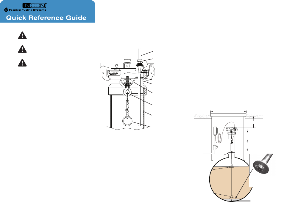
PRODUCT
Ullage
Install Probe
1/4" (6.4 mm) Above
Bottom of Tank
Water Float
Product
Float
6.0" (152 mm) Minimum
14" (356 mm) Minimum
Manhole Cover
8.0" (203 mm)
Reference
5"(127 mm)
Minimum
N.T.S.
Spacer
Warning
Warning
Warning
Suspended Probe Installation
Remove and Save
E-Clip and washer
to install floats
Split Ring
Safety
Always lock out and tag electrical
circuit breakers while installing or
servicing this equipment.
Follow all federal, state and local
laws governing the installation of
this product.
Always secure the work area from
moving vehicles.
Purpose of this Guide
The purpose of this guide is to show basic installation
information for magnetostrictive probes, floats and
installation kits offered by Franklin Fueling Systems.
For more detailed information, refer to manual
000-2081, TSP-LL2 Magnetostrictive Probe Installation.
This and other related manuals are available on the
web at www.franklinfueling.com –Service –Technical
Documentation–Fuel Management Systems.
Types of probes
• Level / Leak Detection
• Inventory-Specific
Probe Length
The probe model number indicates its length. The
model numbers are in the form TSP-LL2-xxx, where
xxx = the length of the probe shaft (not including probe
head) in inches. Consider riser height and overhead
clearance when selecting probe length.
For example, the TSP-LL2-101 is for 8’ (96") tanks.
Float Kits
Floats are available for 2", 3" and 4" risers, for gasoline
or diesel. (LPG and chemical floats also available).
Each float kit includes a product and water float. Order
one float set for each LL2 Mag probe.
• Product floats are white (clear)
• Gasoline water floats are red.
• Diesel water floats are blue
Probe Installation Kits
Installation kits are available for 2" and 4" risers with
either NPT or BSP threads. Kits for above-ground tank
probes and LPG probes are also available.
Mounting Suspended Probes
Leak Detection Probes
must be suspended ¼" above
the bottom of the tank using one of the appropriate
installation kits.
R
Riser Cap Adapter
Support Plate
Riser Pipe
Eyebolt
Probe Cable
Rubber Grommet
Suspended Probe Installation Detail (TSP-K4A shown)
Installation
1. Measure from the top of the riser pipe to the
bottom of the tank-record value in inches.
2. Measure the overall length of Probe.
3. Subtract the probe length from the distance
measured from the top of the riser pipe to
the bottom of the tank, and then add 1/2 inch
to this distance. This value is the
TOTAL
LENGTH OF THE CHAIN INCLUDING THE
SPLIT RING AND ADJUSTMENT EYEBOLT.
4. The suspension chain must be cut to the exact
length required.
5. Remove the split ring from the end of the chain
and cut the chain to the correct length.
6. Reattach the split ring to its end and measure
the total overall length to make certain that it is
within one half inch of correct value.
7. Apply pipe sealant to the male riser threads.
8. Screw the riser cap adapter into the top of the
riser pipe. Tighten to 20-25 ft-lbs.
9. Connect the probe to the split ring on the chain.
10. Carefully position the steel support plate
containing the rubber grommet and insulating
shoulder washer into the riser cap.
11. Guide the probe cable through the rubber
grommet.
12. Unscrew the adjusting eyebolt so the probe
just touches the bottom of the tank.
13. Turn the wing nut clockwise, 4 full turns (only).
This will raise the probe approximately ¼"
above the bottom of the tank.
14. Push the probe cable through the compression
fitting on the probe cap.
15. Install the probe cap on the riser cap adapter
such that the compression fitting is aligned with
the rubber grommet.
16. Tighten compression fitting to make a
watertight seal.
Compression Fitting