Installation sequence – Franklin Fueling Systems TSP-DIS User Manual
Page 3
Installation Sequence:
1. * Install riser pipe, manhole.
2. Install conduit, EYS fittings, and weatherproof
junction box.
3. Shut off power.
ELECTRICAL DANGER Avoid electrical
shock hazards: ensure all power
going to the ATG console is turned off,
tagged, and locked-out at the power
panel before doing any maintenance or
installation work at the ATG console
4. Interstitial installation – Figure 2, measure the
length of the riser pipe + 1.5 x diameter of tank
= _________total length. Mark this length on the
cable and pull it through the TSP-KI2 riser cap
cord-grip until the mark is 12 inches (30.5 cm)
above the fitting. Tie one end of the pull-wire to the
sensor pull cap and pull the wire until the sensor
cable moves just above the cord-grip (leave the
pull wire in place: loop the wire around the cable)
and then tighten the fitting.
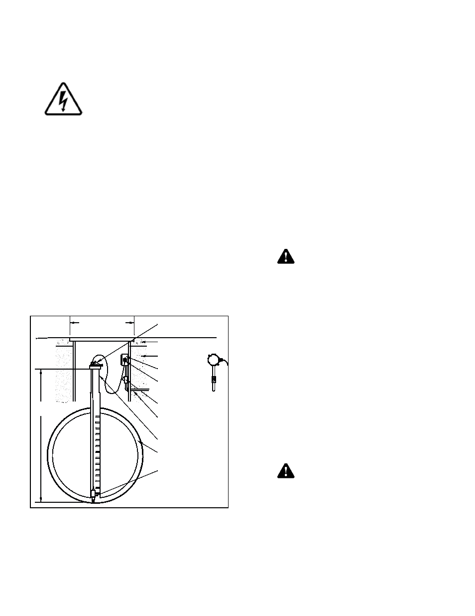
5. Interstitial installation (Figure 3), measure the
INSTALL HEIGHT needed and add 1.5 inches for
the riser cap = total height.
Mark the total height required on the sensor cable, and
pull the cable through the TSP-KI2 riser cap until the mark
shows at the top of the cord grip fitting. Tighten the fitting
and lower the sensor into the interstitial area of the tank as
shown in Figure 3.
Double
Wall
Steel
Tank
Install Height
(Measured)
Manhole
Cover For
14 inch (35.56 cm)
Min. Dia. Manhole
1/2 or 3/4 Inch Conduit
2 Inch (50.8 Mm)
Riser Pipe
Eys Seal
Fitting
Interstitial
Area (Dry)
TSP-DIS Or
TSP-EIS
Sensor
Clean Fill Material
(Gravel Typical)
TSP-K I2 Riser Cap
(With Cord Grip -
Compression Fitting)
Concrete Slab
Per NFPA 30
Weatherproof
Junction Box
Compression
Fitting
(Cord Grip)
Figure 3: Installation in double-Walled Steel Tanks
6. Pull the sensor cables through the cord grip fitting
at the junction box and tighten all remaining cord-
grip fittings. Trim wire/cables to a 6 or 8 inch (15
or 20 cm) service-loop and splice the sensor and
console wires together per Figure 4 .
7. Power up console for next step.
8. Test sensor (verify that an alarm is produced at
ATG console), if it does produce an alarm, seal
EYS seal fittings and electrical connectors with
epoxy.
9. Turn off power again if other devices are to be
installed (Repeat Step 3).
10. Reinstall all safety covers and guards, junction
box gasket and covers – use pipe-dope to seal all
fitting threads.
11. Install the manhole cover.
12. Record the location where the sensor was
installed on the chart on the back page of these
instructions. This information will be needed when
programming the ATG.
13. Turn on power and program the ATG – Ref: all
relating to Sensors in the Setup / Programming &
Installation manuals.
General Installation Notes
* Steel double-walled tanks: codes may require a non-
conductive isolation-bushing be installed between the tank
and riser pipe.
It is the installer’s responsibility to
comply with all applicable federal, state
and local codes. Failure to do so may
create an Environmental Hazard.
Plan your conduit routing. Dig trenches as necessary to
install conduit from each junction box to the Intrinsically
Safe (I.S.) knockouts at the ATG console. You must
install a weatherproof, electrical junction box inside each
manhole. The junction box should be installed high on the
manhole wall to prevent it from being submerged during
heavy rains.
* Fill the bottom of the manhole with crushed stone to
facilitate drainage when the sensor is installed in the
interstitial space of a steel tank. Do not cover the top of
the riser cap with fill material, it must remain accessible for
service / sensor installation.
The conduit may enter the manhole either from the bottom
or the side.
A junction box may be used inside of the building as a pull
box to combine several sensor cables. If this is done, then
only one I.S. conduit knockout will be used.
WARNING Conduits must have EYS
seal fittings installed in accordance
with NFPA 70 (National Electric Code)
and NFPA 30A (Automotive and Marine
Service Station Code). Failure to seal
conduits in accordance with NFPA 30A,
and NFPA 70 could allow flammable
vapors to travel through the conduit in
the ATG console. An explosion could
result causing serious injury, property
loss, or death.
Caution
Warning
Caution
Warning
3