Electrical wiring – Franklin Fueling Systems TSP-HFS User Manual
Page 3
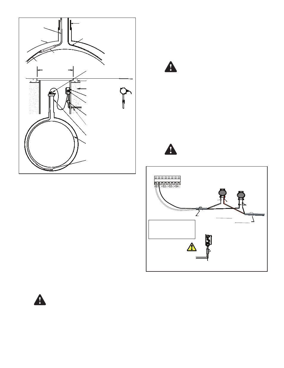
Double Wall
Fiberglass
Tank
Manhole
Cover For
14 Inch (35.56 cm)
Min. Dia. Manhole
1/2 or 3/4 Inch Conduit
2 Inch (50.8 mm) Riser Pipe
TSP-HFS
Sensor
Eys Seal
Fitting
Interstitial Area (Dry)
TSP-K12 Riser Cap
(With Cord Grip -
Compression Fitting)
Clean Fill Material
(Gravel Typical)
Concrete Slab
Per NFPA 30
Weatherproof
Junction Box
Compression
Fitting
(Cord Grip)
Annular Space
Interstitial Sensor
(TSP-HFS)
Pull Wire
Doublewall
Fiberglass Tank
Sensor Cable
Pull Wire
Riser Pipe
Figure 2: Installation in Double-Walled Steel Tanks
6. Trim wire / cables to a 6 or 8 inch (15 or 20 cm)
service-loop, and splice the sensor and console
cable / wires together as shown in Figure 3.
7. Power up console for next step.
8. Test sensor (verify that an alarm is produced at ATG
console), if it does produce an alarm, seal EYS seal
fittings and electrical connectors with epoxy.
9. Turn off power again if other devices are to be
installed (Repeat Step 3).
10. Reinstall all safety covers and guards, junction
box gasket and covers – use pipe-dope to seal all
fitting threads.
11. Install the manhole cover.
12. Record the location where the sensor was
installed on the chart on the last page of these
instructions.
13. Turn on power and program the alarm console .
General Installation Notes
It is the installer’s responsibility to
comply with all applicable federal, state
and local codes. Failure to do so may
create an Environmental Hazard.
Plan your conduit routing. Dig trenches as needed to install
conduit from each manhole junction box to the Intrinsically
Safe (I.S.) knockouts at the alarm console. The conduit
may enter the manhole either from its bottom or through its
side. A junction box inside of the building can be used as a
pull box to combine several sensor cables. If this is done,
then only one I.S. conduit knockout will be used.
Conduits must have EYS seal fittings
installed in accordance with NFPA
70 (National Electric Code) and NFPA
30A (Automotive and Marine Service
Station Code). Failure to seal conduits in
accordance with NFPA 30A, and NFPA 70
could allow flammable vapors to travel
through the conduit in the ATG console.
An explosion could result causing
serious injury, property loss, or death.
You must install a weatherproof, electrical junction
box inside each manhole. The junction box should be
installed high on the manhole wall to prevent it from being
submerged during heavy rains.
Seal all threaded fittings and conduit
threads to produce a weatherproof seal
during installation/maintenance.
Electrical Wiring
2 wires/cable from console
2-conductor cable from sensor
J-box
From 2-wire sensor
IN(WHT)
GND(BLK)
Insert the unstripped wires fully
into the self-sealing, no-strip
electrical connector.
Use slip-joint pliers and seat
the black portion to make a
good electrical connection
IN
(Red)
IN
(White)
GND
(BLK)
Note: 2-wire sensor wire may
be Red and Black. Attach the
red sensor wire to the white
cable wire.
Figure 3: TSP-HFS Wiring
Refer to the console installation manual and see Figure 3
(above) for sensor wiring details. Two-wire sensor cable
does not have a red (power) conductor, therefore, the red
sensor wire should be spliced with the white cable wire. If
a 3-conductor Alpha cable is used, the red conductor can
be clipped or taped back on both ends.
Warning
Warning
Caution
3