Overview, Testing the tsp-hfs, Materials required – Franklin Fueling Systems TSP-HFS User Manual
Page 2: Installation sequence
Overview
The TSP-HFS is a liquid sensor that is used to detect the
presence of a liquid in the normally dry Class 1, Division 1,
Group D Hazardous Areas of the interstitial area of double-
wall storage tanks. The sensor is supplied with electrical
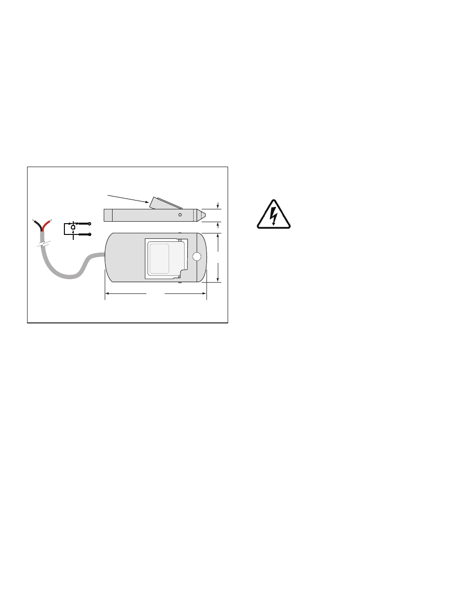
connectors, 25 feet of cable, and a cord-grip fitting (see
diagrams). The TSP-HFS uses magnetic-float / reed-switch
technology (the sensor must lay flat so the float can rise
freely with the level of a liquid).
When the float rises more than approximately 1/2 of an
inch, the magnetically sensitive reed switch will open. An
open circuit is recognized as an alarm-condition at the
intrinsically safe (I.S) leak detection circuits of the FFS
(Franklin Fueling Systems) S940 alarm console.
Reed float switch opens when float
moves up approiximately 1/2" (13 mm)
(Red)
(Blk)
Magnetic
(Red)
(Blk)
C
NC
Gnd
In
3"
(76mm)
1.5"
(38 mm)
0.375"
(9.5 mm)
Figure 1: TSP-HFS Dimensions
Testing the TSP-HFS
Testing this device is a matter of moving the float away
from alignment with the sensor body. This should cause
an alarm at the S940 console. Test the sensor for proper
operation on a yearly basis, or more frequently per local
code.
Materials Required
• Optional – TSP-DB1 Epoxy Seal kit for no-strip electrical
connectors – recommended for sites: within flood zones,
high groundwater tables or with poor drainage.
• 1/2 or 3/4 inch NPT (National Pipe Thread, tapered),
Rigid Metal Conduit (RMC) or nonmetallic (PVC) conduit
if allowed by local codes.
• EYS Seal fittings and Epoxy to fill the fitting after
operational testing is completed.
• Weatherproof junction Box, gasket, and cover, plus a
3/4 to 1/2 inch NPT reducing bushing if 1/2 inch RMC is
used – see the ATG Installation Guide for recommended
electrical Junction Boxes.
• Wire: THHN, TFFN or THWN, 18 AWG, White & Black,
or Alpha Cable # 58411, 0.114 O.D. – 1,500 feet (457
meters) max. length. Alpha cable #58411 must be use
with nonmettalic conduit.
• Slip joint pliers to seat the no-strip, self-sealing wire
connectors – connectors are supplied with the sensor.
• UL Classified Thread Sealant or pipe dope.
• *TSP-KI2 Riser Cap for 2-inch riser pipes, includes a
pre-installed 1/2 inch NPT compression gland (cord grip)
fitting. Other riser caps are available for different riser
pipe sizes – consult your factory rep.
• * Riser pipe – 2 inch min. with all rough edges
removed / deburred from the inner edges.
* Needed for installation in UST interstitial areas (Figure 2)
Installation Sequence
1. Install Riser Pipe, Manhole.
2. Install conduit, EYS fittings, and weatherproof
junction box.
3. Shut off power.
ELECTRICAL DANGER Avoid electrical
shock hazards: ensure all power
going to the ATG console is turned off,
tagged, and locked-out at the power
panel before doing any maintenance or
installation work at the ATG console.
4. Run a pull-wire down the riser and around the
inner tank. You will need access to both ends of
the pull wire.
5. Measure the length of the riser pipe + 1.5 x
diameter of tank = _________total length. Mark
this length on the cable and pull it through the
TSP-KI2 riser cap cord-grip until the mark is 12
inches (30.5 cm) above the fitting. Tie one end of
the pull-wire to the sensor pull cap and pull the
wire until the sensor cable moves just above the
cord-grip (leave the pull wire in place: loop the wire
around the cable) and then tighten the fitting.
2