Overview, Testing the sensor, Materials required – Franklin Fueling Systems TSP-MWS User Manual
Page 2: Installation sequence
Overview
The TSP-MWS sensor is an intelligent BriteSensor ® that
is used to monitor groundwater for the presence of liquid
hydrocarbons (product).
These sensors are installed suspended in the groundwater
of monitoring wells around tanks and use intrinsically safe
(I.S) leak detection circuits – approved for use in these
Class 1, Division 1, Group D Hazardous Areas.
The TSP-MWS sensors have a float at the base that
monitors for the presence of ground water—a dry sensor
cannot detect liquid hydrocarbons that float on the surface
of groundwater. The sensors also have a conductive
polymer strip along its length, which reacts specifically with
liquid hydrocarbons (causing an increase in the electrical
resistance of the polymer strip).
TSP-MWS
Discriminating
Monitoring well
Sensor
(Britesensor ®)
Sensor
Model-lengths:
TSP-MWS-10 =
10 foot length (3 m)
TSP-MWS-15 =
15 foot length (4.6 m)
TSP-MWS-20 =
20 foot length (6 m)
TSP-MWS-25 =
25 foot length (7.6 m)
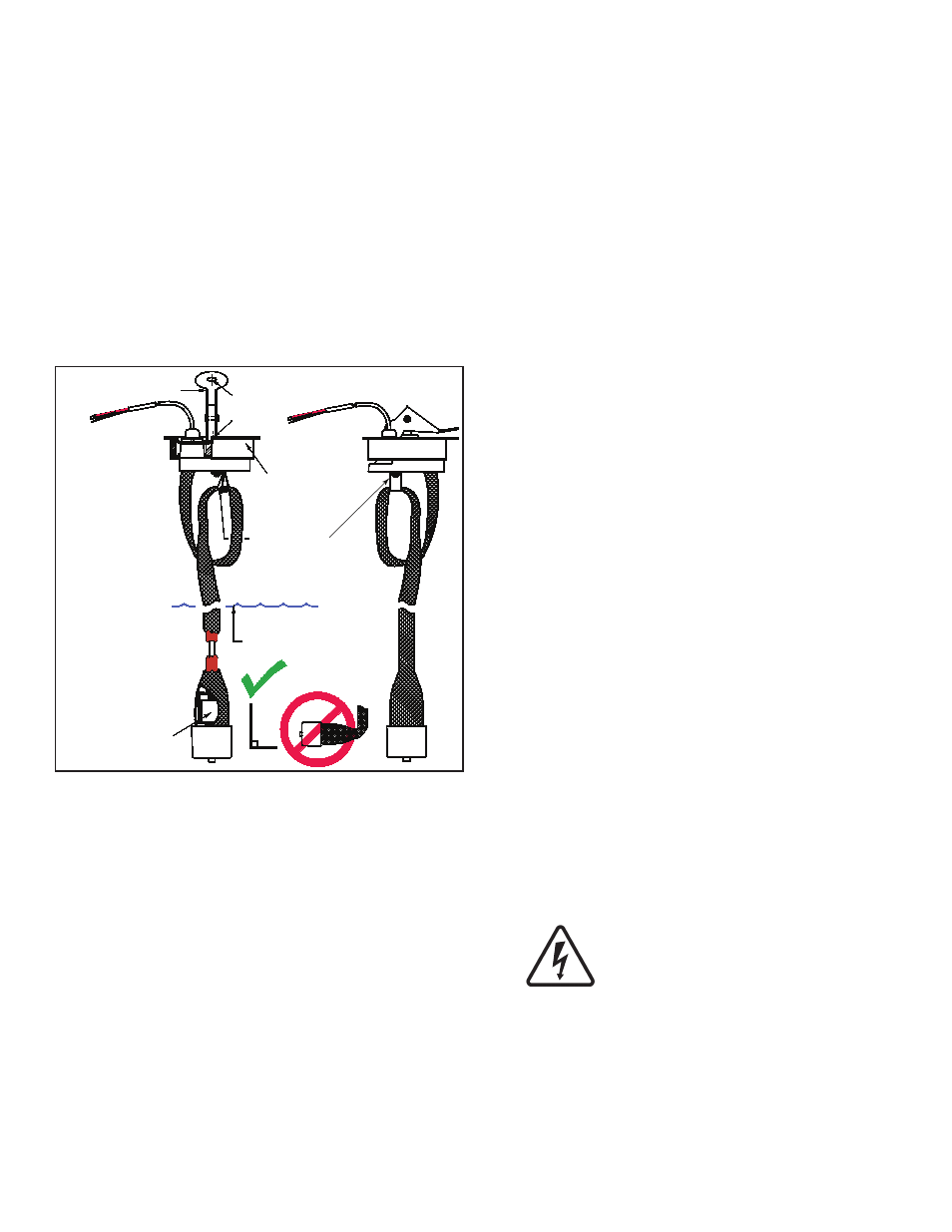
Sensor must be installed
“suspended in groundwater”
4 inch (102 mm)
Locking riser cap
(part of sensor)
Retainer to loop
excess sensor length
Dry season groundwater level
Internal
low water level
float switch
Lever
Thru holes
For locking
Figure 1: TSP-MWS Sensor Dimensions
Like other BriteSensors, The TSP-MWS sensors have a
microprocessor that analyzes the environmental conditions
at the sensor and transmits this data to the Automatic
Tank Gauge console. The TSP-MWS sensors detect and
communicates:
A dry well alarm (from the float at its base),
•
PRODUCT present (from the polymer strip),
•
NORMAL no-alarm state (no product present and
•
sensor is submerged in groundwater),
Plus it transmits a specific sensor ID code.
•
An attached 4 inch riser cap, no-strip electrical wire
connectors, 25 feet of cable attached to the sensor, a
Model ID tag, and a cord-grip fitting (for connection to a
weatherproof electrical junction box) are supplied with the
TSP-MWS sensor (see diagrams).
Testing the Sensor
Turn the bottom of the sensor up 180 degrees so the
bottom faces up, wait 5 seconds, and let the sensor
hang dry again – a DRY WELL alarm will be generated.
Although sensors may be washed and recovered after
exposure to liquid hydrocarbons, we recommend not
testing for product alarms because of the long after-test
recovery period involved.
Test sensors on a yearly basis, or more frequently if
required by local code.
Test the groundwater for the presence of liquid
hydrocarbons BEFORE installing the monitoring well
sensor (give copy of results to site owner / manager).
Materials Required
Optional – TSP-DB1 Epoxy Seal kit for no-strip electrical
•
connectors – recommended for sites: within flood zones,
high groundwater tables, with poor drainage, or when
Junction Boxes are not used.
Well Screen Pipe – Schedule 40 PVC, 4 inch (102 mm)
•
diameter.
1/2 or 3/4 inch NPT (National Pipe Thread, tapered),
•
Rigid Metal Conduit (RMC) or nonmetallic (PVC) if
allowed by local code.
EYS Seal fittings and epoxy to fill the fitting after
•
operational testing is completed.
Weatherproof junction box, gasket, and cover, plus a
•
3/4 to 1/2 inch NPT reducing bushing if 1/2 inch RMC is
used – see the ATG Installation Guide for recommended
electrical Junction Boxes.
Wire: THHN, TFFN or THWN, 18 AWG: Red, White, &
•
Black, or Alpha Cable # 58113,(3.3 mm) 0.131” O.D. –
1,500 feet (457 meters) max. length. Alpha cable 58113
must be used if using non-metallic (PVC) conduit.
Slip joint pliers to seat the no-strip, self-sealing wire
•
connectors – connectors are supplied with the sensor.
U.L. classified thread sealant or pipe dope.
•
Installation Sequence
1. Install Sump.
2. Install conduit, EYS fittings, and weatherproof
junction box.
3 Shut off power.
ELECTRICAL DANGER Avoid electrical
shock hazards: ensure all power
going to the ATG console is turned off,
tagged, and locked-out at the power
panel before doing any maintenance or
installation work at the ATG console.
4. Install the sensor cable through the supplied
compression fitting.
5. Install the compression fitting at the waterproof
junction box and tighten the cord-grip fitting.
6. Trim wire/cables at the junction box to a 6 or 8 inch
length (15 or 20 cm) or service-loop, and splice the
sensor and console wires together per Figure 3.
2