Electrical wiring – Franklin Fueling Systems TSP-HLS User Manual
Page 3
7. Test sensor (rotate float end up to verify that an
alarm is produced at ATG console). If the sensor
does produce an alarm, seal EYS seal fittings
with epoxy.
8. Turn power off again if other devices are to be
installed (Repeat Step 3)
9. Reinstall all safety covers and guards, junction
box gasket and covers – use pipe-dope to seal all
fitting threads.
10. Adjust the ACTUATION LEVEL (
FLOAT HeigHT)
to
equal the High Level Alarm level for this Tank .
a. Loosen the ⅞ inch swage locknuts
b. Move the shaft to set float height
c. Retighten the swage locknuts to hold position.
11. Install the manhole cover.
12.
Record the location where the sensor was
installed (TANK), and the Float Height = High
Level Alarm
Level on the back page of this
document. This information is needed when
programming the ATG.
13. Turn power on and program the ATG – Refer to
Sensors in the console Setup / Programming &
Installation manuals.
general installation Notes
it is the installer’s responsibility to
comply with all applicable federal, state
and local codes. Failure to do so may
create an environmental Hazard.
Fill the bottom of the manhole with crushed stone to
facilitate drainage. Do not cover the sensor or bung access
hole with fill material, it must remain accessible for sensor
installation and for service / testing.
Plan your conduit routing. Dig trenches as necessary
to install conduit from each manhole junction box to the
Intrinsically Safe (I.S.) knockouts at the ATG console. The
conduit may enter the manhole either from its bottom or
through its side. A junction box inside of the building as a
pull box to combine several sensor cables. If this is done,
then only one I.S. conduit knockout will be used.
Conduits must have EYS seal fittings
installed in accordance with NFPA
70 (National electric Code) and NFPA
30A (Automotive and Marine Service
Station Code). Failure to seal conduits
in accordance with NFPA 30A, and
NFPA 70 could allow flammable vapors
to travel through the conduit in the
ATg console. An explosion could result
causing serious injury, property loss,
or death.
You must install a weatherproof, electrical junction
box inside each manhole. The junction box should be
installed high on the manhole wall to prevent it from being
submerged during heavy rains.
Note: Seal all threaded fittings and conduit fittings to
produce a weatherproof seal.
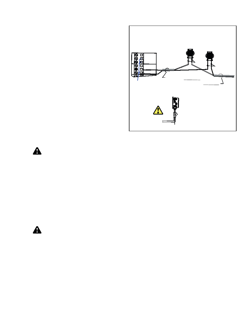
2 wires/cable from console
2-conductor cable from sensor
J-box
From 2-wire sensor
SE
NS
OR
N
IN(WHT)
Only remove the
jumper link between:
in (wht) & gnd (blk),
when a sensor
channel is wired
Note: The
PWR (red)
terminal is
not used with
2-wire sensors
GND(BLK)
PWR(RED)
PWR(RED)
SE
NS
OR
1
IN(WHT)
GND(BLK)
Insert the unstripped wires fully
into the self-sealing, no-strip
electrical connector.
Use slip-joint pliers and seat
the black portion to make a
good electrical connection
IN
(WHT)
GND
(BLK)
Figure 3: Sensor Wiring
electrical Wiring
Reference the ATG Installation Manual and see
Figure 3
(above) for TSP‑HLS sensor wiring details. The two‑wire
TSP‑HLS sensor does not have a red (power) conductor,
therefore, the PWR (RED) interface terminal at the console
is not used. If a 3-conductor Alpha cable is used, the red
conductor can be clipped or taped back on both ends.
Caution
Warning
Caution
Warning
3