Overview, Testing the tsp -hls, Materials & data required – Franklin Fueling Systems TSP-HLS User Manual
Page 2: Installation sequence
Overview
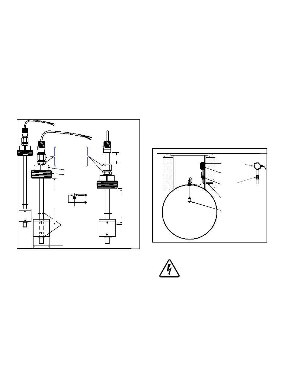
The TSP ‑HLS is a standard sensor that is used to detect
a high liquid level condition within storage tanks (for Class
1, Division 1, Group D Hazardous Area / Environments
such as fuel storage tanks). The sensor is available in two
standard lengths: TSP‑HLS‑15 = 15 inch (381 mm) and
TSP‑HLS‑30 = 30 inch (762 mm). The sensor is supplied
with electrical connectors, 25 feet (7.5 meters) of attached
cable, and a cord‑grip fitting.
The
TSP-HLS sensor uses magnetic‑float / reed‑switch
technology for liquid detection. The wetted portion of
the sensor is constructed of stainless steel and nitrophyl
(float). When the float rises about ½ inch (12.5 mm), the
magnetically‑sensitive reed switch opens (see
Figure 1).
An open circuit is an alarm‑condition (at the intrinsically-
safe,
sensor interface terminals inside the Franklin Fueling
Systems ATG console).
1.86 inch (47.25 mm)
Dia. float
(Black)
Square (33.25 mm)
2 inch NPT fitting
Magnetic reed
float switch circuit
opens when float
moves up
Typical sensor
input interface
(Channel n):
(WHT)
(BLK)
TSP-HLS-XX
CLOSED
OPEN
Float retainer
C-clips
HIGH LEVEL SENSOR
(Standard Sensor)
TSP-HLS
7/8 inch (22.23 mm)
Swage locknuts to set
Actuation length (Float
height alarm setpoint)
adjusted length L
NC
C
GND
TSP-HLS-XX
OPEN
CLOSED
Adjusted
Length L
IN
(White)
C LOSED
OP
EN
Model number
value indicates
approximate
maximum
adjusted length
in inches
Model number
value minus (-)
length L = Float
height (high alarm
setpoint) in inches
Figure 1: TSP-HLS Dimensions and Setup
Testing the TSP -HLS
Rotate the sensor 180 degrees (float up) to cause an
alarm at the ATG console. Test the sensor for proper
operation on a yearly basis, or as required per local code.
Materials & Data Required
• Optional – TSP‑DB1 Epoxy Seal kit for no‑strip electrical
connectors – recommended for sites: within flood
zones, high groundwater tables, with poor drainage, or
when Junction Boxes are not used
1/2 or 3/4 inch NPT (National Pipe Thread, tapered),
•
Rigid Metal Conduit (RMC) or nonmetallic (PVC) conduit
if allowed by local code.
EYS Seal fittings and epoxy to fill the fitting after
•
operational testing is completed.
Weatherproof junction box, gasket, and cover, plus a
•
3/4 to 1/2 inch NPT reducing bushing
if 1/2 inch RMC is
used – see the ATG Installation Guide for recommended
electrical Junction Boxes
Wire: THHN, TFFN or THWN, 18 AWG, White & Black,
•
or Alpha Cable # 58411, 0.114” O.D. (2.9 mm) – 1,500
feet (457 meters) max. length If using nonmetallic (PVC)
conduit, Alpha cable 58411 must be used.
Slip joint pliers to seat the no‑strip, self‑sealing wire
•
connectors – connectors are supplied with the sensor
Standard adjustable or pipe wrench for a 2 inch square
•
fitting
U.L. classified thread sealant or pipe dope.
•
Tank Strapping Table (Tank Chart) to set the
•
High Level
Alarm
Two 7/8 inch (23 mm) hex wrenches to adjust
•
FLOAT
HeigHT.
installation Sequence:
1. Install manhole.
2. Install conduit, EYS fittings, and weatherproof
junction box
Tank
Eys seal
Fitting
½ or ¾ inch conduit
TSP-HLS
Sensor
Weatherproof
Junction box
Compression
Fitting
(Cord grip)
Figure 2: TSP-HLS Installation
3. Turn off power.
eLeCTRiCAL DANgeR Avoid electrical
shock hazards: ensure all power
going to the ATg console is turned off,
tagged, and locked-out at the power
panel before doing any maintenance or
installation work at the ATg console
4. Pull the sensor cables through the cord grip fitting
at the junction box. Leave enough cable to allow
installation of the sensor in the tank: the sensor
will be tested before actual in‑tank installation.
5. Tighten cord‑grip fitting at the junction box and trim
the wire / cables within the junction box to a 6 or 8
inch (15 or 20 cm) length, then splice the sensor
and console cable / wires together as shown in
Figure 3.
6. Turn console power on for sensor testing.
2