Materials, Dimensions, Pressure ratings – Cla-Val 393-01/3693-01 User Manual
Page 7
393-01/3693-01 Purchase Specifications
The 393-01/3693-01 Electronic Actuated Pressure Reducing and Solenoid Shutoff Control Valve shall have an integral hydraulic and electronic
controller contained in a NEMA 4 enclosure to provide the interface between remote telemetry and valve control. It will compare a selectable
remote analog or local setpoint with a process variable signal or an internal position sensor signal and automatically adjust the hydraulic pilot
control until the main control valve reaches desired setpoint.
The electronic actuator will supply loop power for the process variable signal. Retransmission of the process variable shall be with an isolated non-
powered analog signal. The actuator speed will be infinitely adjustable between 1/3 and 5 RPM and will have an adjustable dead band. In the
event of an erroneous communications signal, actuator output will be capable of being limited to a predetermined process variable value. If these
signals (SP and /or PV) are lost, the valve shall remain under control of the pressure reducing hydraulic control. The actuator can also be pro-
grammed to drive the main valve to the open or closed position if these signals are lost.
All setup and adjustments will be capable of being made prior to placing the valve into service using actuator test points for signal measurement
and subsequent calibration. Actuator diagnostics will be displayed using LEDs. Manual operation of the hydraulic pilot will be fully adjustable
using a non-rotating handwheel.
The Electronic Actuated Pressure Reducing and Solenoid Shut-Off Control Valve shall be the Cla-Val Model 393-01/3693-01 as manufactured
by Cla-Val, Newport Beach, CA.
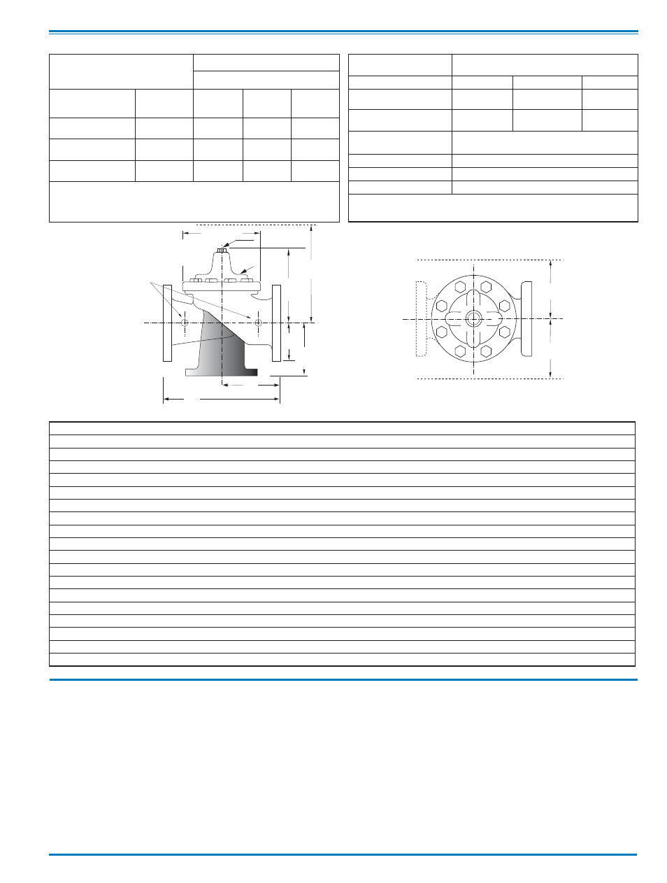
Model 3693-01 Dimensions
(In Inches)
Materials
EE
D
E
Inlet
DD
AA
X
100-20
Flanged
F
A
C
(MAX)
K
J
H
Inlet
Outlet
FF
B
(Diameter)
Dimensions
(In inches)
Component
Standard Material Combinations
Body & Cover
Ductile Iron
Cast Steel
Bronze
Available Sizes
3" - 48"
3" - 16"
3" - 16"
Disc Retainer &
Diaphragm Washer
Cast Iron
Cast Steel
Bronze
Trim: Disc Guide,
Seat & Cover Bearing
Bronze is Standard
Stainless Steel is Optional
Disc
Buna-N
®
Rubber
Diaphragm
Nylon Reinforced Buna-N
®
Rubber
Stem, Nut & Spring
Stainless Steel
For material options not listed, consult factory.
Cla-Val manufactures valves in more than 50 different alloys.
Y
Z
Pressure Ratings
(Recommended Maximum Pressure - psi)
Valve Body & Cover
Pressure Class
Flanged
Grade
Material
ANSI
Standards*
150
Class
300
Class
ASTM A536
Ductile Iron
B16.42
250
400
ASTM A216-WCB
Cast Steel
B16.5
285
400
ASTM B62
Bronze
B16.24
225
400
Note:
* ANSI standards are for flange dimensions only.
Flanged valves are available faced but not drilled.
Valves for higher pressure are available; consult factory for details
Note: The top two flange holes on valve sizes 36 thru 48 are threaded to 1 1/2"-6 UNC.
*Consult Factory
Valve Size
(Inches)
3
4
6
8
10
12
14
16
18
20
24
30
36
42
48
A 150 ANSI
10.25
13.88
17.75
21.38
26.00
30.00
34.25
35.00
42.12
48.00
48.00
63.25
65.00
76.00
94.50
AA 300 ANSI
11.00
14.50
18.62
22.38
27.38
31.50
35.75
36.62
43.63
49.62
49.75
63.75
67.00
76.00
94.50
B Dia.
6.62
9.12
11.50
15.75
20.00
23.62
27.47
28.00
35.44
35.44
35.44
53.19
56.00
66.00
66.00
C Max.
7.00
8.62
11.62
15.00
17.88
21.00
20.88
25.75
25.00
31.00
31.00
43.94
54.60
61.50
61.50
D 150 ANSI
—
6.94
8.88
10.69
CF*
CF*
CF*
CF*
CF*
CF*
CF*
—
—
—
—
DD 300 ANSI
—
7.25
9.38
11.19
CF*
CF*
CF*
CF*
CF*
CF*
CF*
—
—
—
—
E 150 ANSI
—
5.50
6.75
7.25
CF*
CF*
CF*
CF*
CF*
CF*
CF*
—
—
—
—
EE 300 ANSI
—
5.81
7.25
7.75
CF*
CF*
CF*
CF*
CF*
CF*
CF*
—
—
—
—
F 150 ANSI
3.75
4.50
5.50
6.75
8.00
9.50
11.00
11.75
15.88
14.56
17.00
19.88
25.50
28.00
31.50
FF 300 ANSI
4.12
5.00
6.25
7.50
8.75
10.25
11.50
12.75
15.88
16.06
19.00
22.00
27.50
28.00
31.50
H NPT Body Tapping
.375
.50
.75
.75
1
1
1
1
1
1
1
1
2
2
2
J NPT Cover Center Plug
.50
.50
.75
.75
1
1
1.25
1.25
2
2
2
2
2
2
2
K NPT Cover Tapping
.375
.50
.75
.75
1
1
1
1
1
1
1
1
2
2
2
Stem Travel
0.6
0.8
1.1
1.7
2.3
2.8
3.4
3.4
3.4
4.5
4.5
6.5
7.5
8.5
8.5
Approx. Ship Wt. Lbs.
45
85
195
330
625
900
1250
1380
1500
2551
2733
6500
8545
12450 13100
X Pilot System
13
15
27
30
33
36
36
41
40
46
55
68
79
85
86
Y Pilot System
10
11
18
20
22
24
26
26
30
30
30
39
40
45
47
Z Pilot System
10
11
18
20
22
24
26
26
30
30
30
39
42
47
49