Remote automatic mode – Cla-Val 393-01/3693-01 User Manual
Page 30
8
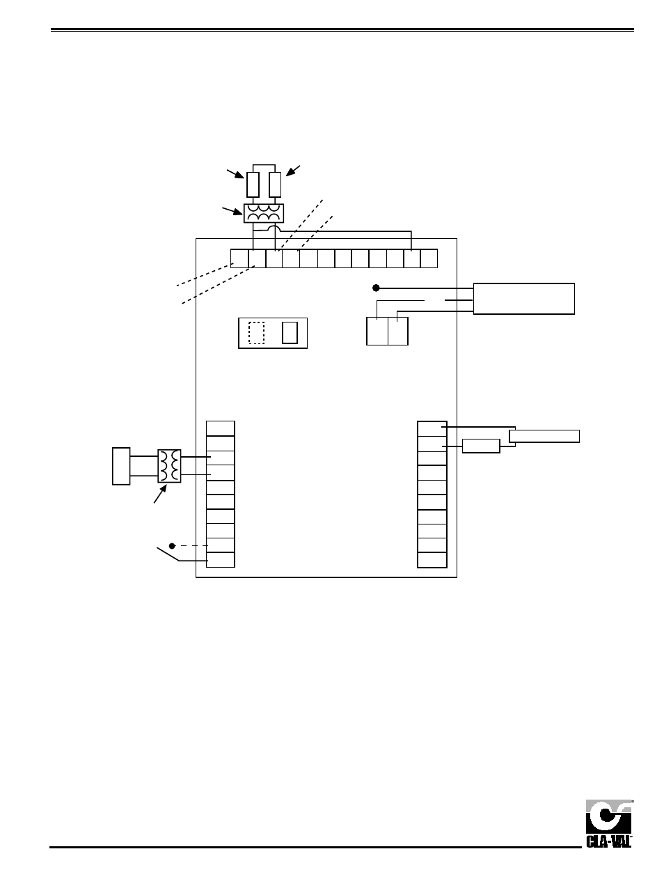
Remote Automatic Mode
Using external PV and external
power supply to power 4-20 mA loop
Power Supply
Process Variable
Loop Isolator
(recommended)
420 mA Pv input +
Isolated +24 VDC
Ground to green
screw in floor
of housing
G
N
L
TB1
1
2
3
4
5
6
7
8
9
10
1
2
3
4
5
6
7
8
9
10
TB3
Isolated 420 mA Transmitter -
Isolated 420 mA Transmitter +
Load
Power Supply
—
+
Remote Setpoint
+
—
Loop Isolator
Optional external
switch to stop
actuator rotation
1. Remote setpoint must be isolated and powered from ecternal source.
2. PV retransmission requires an external power supply within 12 to 36 VDC.
Maximum load = (Power supply VDC - 8 VDC) / .020A.
240AC 120AC
1
2
TB2
120/240 AC Input
TB4
1
2
3
4
5
6
7
8
9
10
11
12
Isolated Common
420 mA PV input —
+
-
+
-
3. A switch may be placed between terminals 9 and 10 on TB3 to interrupt actuator
travel. Contact between 9 and 10 will stop actuator movement.
DO NOT POWER.
- 136-01/636-01 Solenoid Control Valve Quick Manual (2 pages)
- 136-03/636-03 Valve Quick Manual (2 pages)
- 136-01/636-01 Technical Manual (36 pages)
- 136-03/636-03 Technical Manual (36 pages)
- X52E Orifice Plate Assembly (4 pages)
- 49-01/649-01 Quick Manual (2 pages)
- 49-01/649-01 Technical Manual (33 pages)
- 40-01/640-01 Quick Manual (2 pages)
- 40-01/640-01 Technical Manual (28 pages)
- 90-01/690-01 Quick Manual (2 pages)
- 90-01/690-01 Technical Manual (29 pages)
- 90-48/690-48 Quick Manual (2 pages)
- 90-48/690-48 Technical Manual (34 pages)
- 92-01/692-01 Quick Manual (2 pages)
- 92-01/692-01 Technical Manual (28 pages)
- 93-01/693-01 Quick Manual (2 pages)
- 93-01/693-01 Technical Manual (42 pages)
- 590-01/6590-01 Quick Manual (2 pages)
- 590-01/6590-01 Technical Manual (21 pages)
- 60-11/660-11 Quick Manual (1 page)
- 60-11/660-11 Technical Manual (27 pages)
- 61-02/661-02 Technical Manual (34 pages)
- 60-73/660-73 Technical Manual (36 pages)
- 581 Series Quick Manual (2 pages)
- 581 Series Technical Manual (7 pages)
- 81-02/681-02 Quick Manual (2 pages)
- 81-02/681-02 Technical Manual (24 pages)
- 81-01/681-01 Quick Manual (2 pages)
- 81-01/681-01 Technical Manual (24 pages)
- 98-06/698-06 Quick Manual (4 pages)
- 98-06/698-06 Technical Manual (36 pages)
- 43-01/643-01 (35 pages)
- 390-07/3690-07 (40 pages)
- 585 Series (4 pages)
- 584 (2 pages)
- 501A Series (2 pages)
- 501A Series (4 pages)
- 583 (1 page)
- 81-12 (2 pages)
- 582 Series (4 pages)
- 38VB/AR Series (4 pages)
- PC-1 (8 pages)
- 60-32/660-32 (4 pages)
- 60-31/660-31 (4 pages)
- 61-02KO/661-02KO Valve (4 pages)