Voltage at test point vs. current (ma) – Cla-Val 393-01/3693-01 User Manual
Page 27
LED
Function
Microprocessor
This LED is on when power is applied to the microprocessor, and
running
the microprocessor is running. If LED is not on, then verify power to the board,
as well as the SW1 setting on the top board
Actuator Increasing
This LED is on when the actuator is moving in the increasing direction
Actuator Decreasing
This LED is on when the actuator is mowing in the decreasing direction.
Fault
This LED will flash when a fault is present. The LED will flash at a
given rate. If the LED is flashing at 0.5 second intervals, then a LOS
for the remote setpoint is present. If the LED is flashing at 1 second
intervals, then a LOS for the process variable is present. If the LED
is flashing a 2 second intervals, then the remote operation is disabled
because the zero and span positions have not been set.
Red Enable Button
This LED will be on when the enable button and one of the other four
setup push buttons have been pressed at the same time
Minimum Position
This LED will be on when the actuator is at or below its set minimum position.
LS1 Position
This LED will be on when the process variable is at or below its minimum value.
LS2 Position
This LED will be on when the process variable is at or above its maximum value.
Maximum Position
This LED will be on when the actuator is at or above its maximum position.
Test Point
Function
Range
SPD
Speed of the actuator.
A value of 0 to 5 volts will be displayed.
See Figure #4
PSN
The position of the actuator.
A value of 4.49 to 1.57 volts will be displayed
4.49V is minimum and 1.57V is maximum position
CMD
The setpoint command.
If 4 to 20ma current is selected, 0.8 volts to 4 will
be displayed. If 0 to 5 volts, 0 to 10 or local setpoint
volts is selected, then 0 to 5 volts will be displayed.
PV
The process variable.
Input is 4 to 20ma only and a value 0.8 volts
to 4 volts will be displayed.
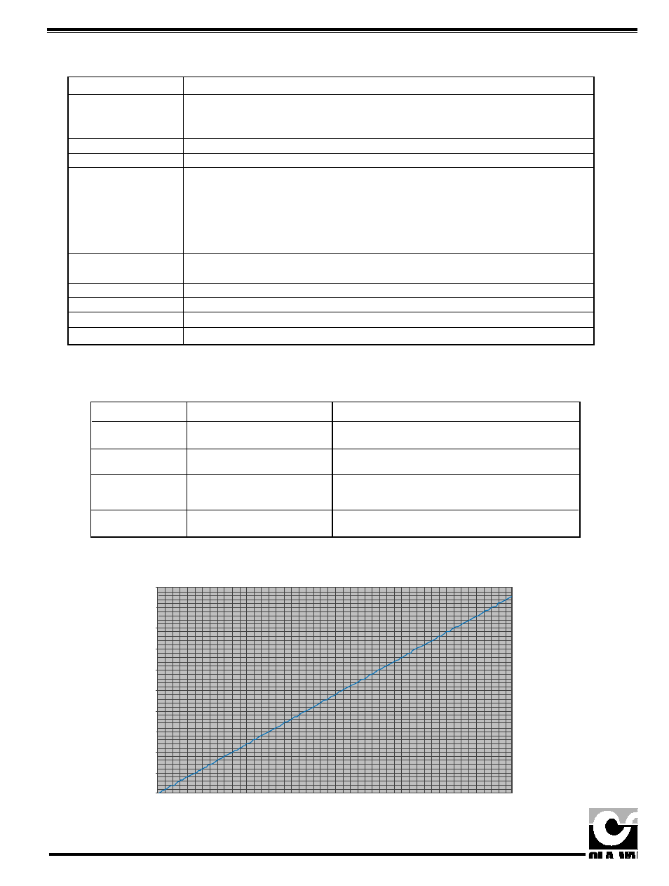
Tests using voltage meter.
There are four test points located on the logic board. The black test point labeled COM is used for the common
connection. Connect a voltage meter to the COM and the appropriate test point. The values of the four red test
points are shown in the following table:
Voltage at Test Point vs. Current (mA)
5.00
4.50
4.00
3.50
3.00
2.50
2.00
1.50
1.00
0.50
0.00
0.00
2.00
4.00
6.00
8.00
10.00
12.00
14.00
16.00
18.00
20.00
22.00
Curreent (mA)
Voltage at Test Point (V) vs Current (mA)
V
oltage at
T
est Point (V)
LED indication.
LEDs are provided to display the status of the actuator. They are located on the logic board. Their functions
are shown in the following table.
5