Appendix, cont’d – Extron Electronics VSC 900_900D User Guide User Manual
Page 46
Appendix, cont’d
VSC 900/900D • Appendix
A-6
50/6
0 H
z
100
-24
0V
0.3
A
R
/R-Y
R
/R-Y
I
N
P
U
T
S
O
U
T
P
U
T
S
G
/Y
2
RG
B/R
-Y,
Y, B
-Y
RG
B
1
G
/Y
B
/B
-Y
B
/B
-Y
H
/H
V
H
/HV
V
V
VID
EO
S-V
IDE
O
D1
R/R
-Y
G/Y
B/B
-Y
H/H
-Y
RS
-23
2
/42
2
G
E
N
L
O
C
K
V
IN
OU
T
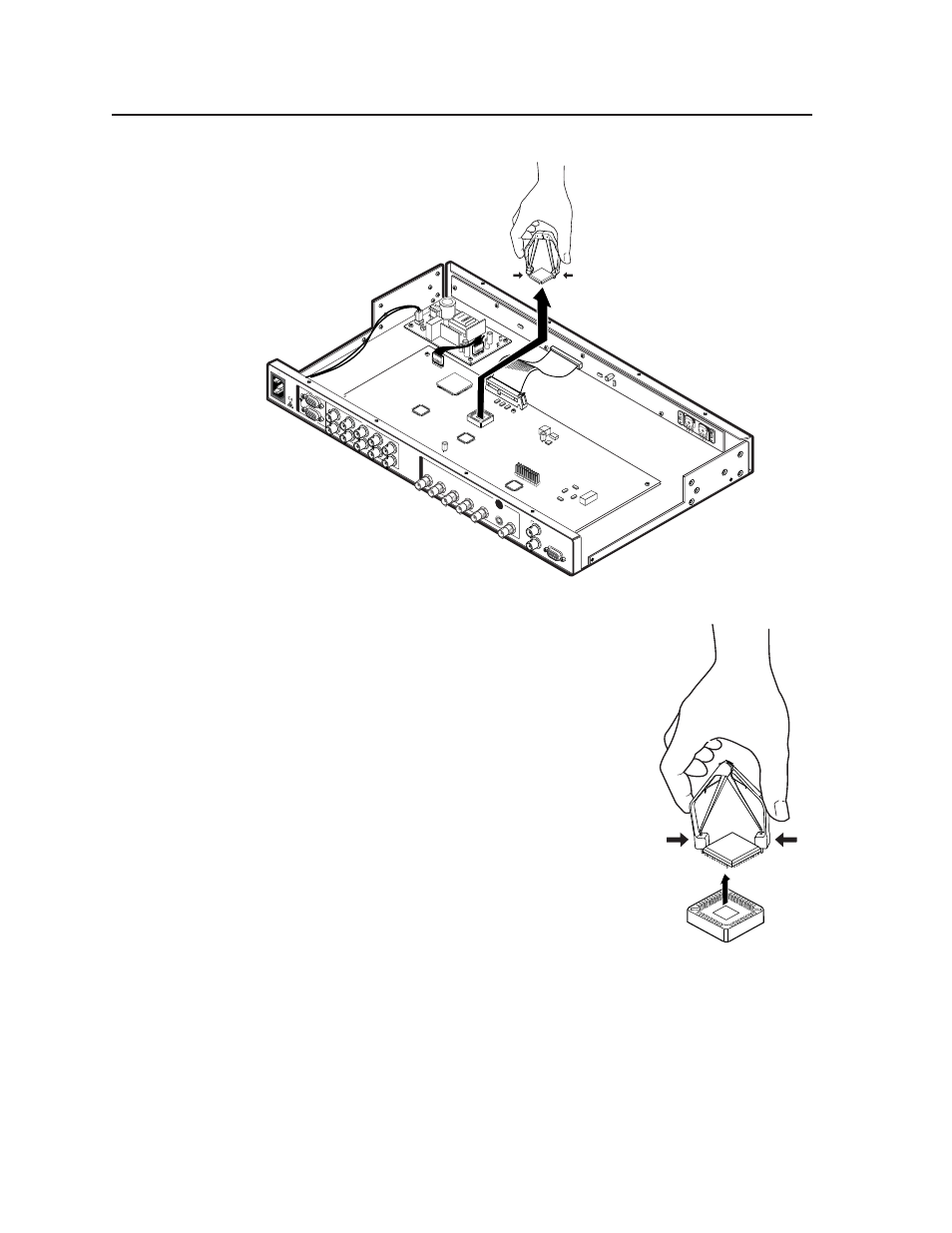
U1
5.
Removal of the U1 IC chip requires a PLCC IC
puller tool. To remove the chip, align the hooks of
a PLCC IC puller tool with the slots located in
opposite ends of the U1 firmware chip.
6.
Insert the hooks into the slots, and squeeze the
tool gently to grasp the chip.
7.
Pull the chip straight out of the socket, and set it
aside.
8.
Align the slots of the new firmware chip with the
angled corners of the socket in the same
orientation as the old chip.
9.
Gently, but firmly, press the chip into place in the
socket.
10.
Replace the top cover on the VSC, and fasten it
with the screws that were removed in step 3.
11.
Rack/furniture mount the scan converter, connect
the input/output cables, and reconnect the AC
power cord.
U1
- FOX Matrix 3200 (132 pages)
- ADA 2-4-6 Series (3 pages)
- ADA 6 Component (2 pages)
- AVT 100 (37 pages)
- AVT 200HD Setup Guide (4 pages)
- AVT 200HD User Guide (118 pages)
- AVTrac (482) User Guide (28 pages)
- CAT 5 Receivers (15 pages)
- CAT 5 Transmitters (15 pages)
- CD 400 (3 pages)
- CD 800 (15 pages)
- CD 900 (19 pages)
- CD 100 (18 pages)
- CSVEQ 100 D (38 pages)
- CSVEQ 100 D (2 pages)
- DA RGB_YUV Series (17 pages)
- CVEQ1, CVEQ1 WM, CVEQ1 AAP (17 pages)
- CVEQ_SVEQ 100 Series Setup Guide (2 pages)
- CVDA 6 EQ MX (3 pages)
- CVDA 6 EQ MX (2 pages)
- CVC 300 (8 pages)
- CVC 200 (4 pages)
- CVC 100 (2 pages)
- DDS 402 (54 pages)
- DDS 100 (54 pages)
- DA AV EQ Series (2 pages)
- DVC 501 SD User Guide (38 pages)
- DVC 501 SD Setup Guide (2 pages)
- DTP T USW 333 User Guide (26 pages)
- DTP T USW 333 Setup Guide (4 pages)
- DTP T USW 233 User Guide (26 pages)
- DTP T USW 233 Setup Guide (4 pages)
- DTP HDMI 330 User Guide (19 pages)
- DTP HDMI 330 Setup Guide (2 pages)
- DTP HDMI 301 User Guide (23 pages)
- DTP HDMI 301 Setup Guide (2 pages)
- DTP HDMI 230 User Guide (19 pages)
- DTP HDMI 230 Setup Guide (2 pages)
- DTP HDMI 230 D User Guide (22 pages)
- DTP DVI 330 User Guide (19 pages)
- DTP DVI 330 Setup Guide (2 pages)
- DTP DVI 301 User Guide (23 pages)
- DTP DVI 301 Setup Guide (2 pages)
- DTP DVI 230 User Guide (19 pages)
- DTP DVI 230 Setup Guide (2 pages)