Extron Electronics VSC 900_900D User Guide User Manual
Page 33
3-3
VSC 900/900D • Serial Communication
Using the command/response tables
The command/response tables on the next page list valid command ASCII codes,
the scan converter’s responses to the host, and a description of the command’s
function or the results of executing the command.
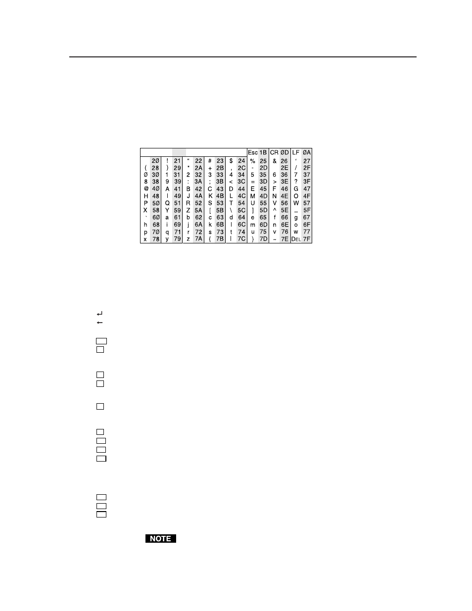
The ASCII to HEX conversion table below is for use with the
command/response tables.
ASCII to HEX Conversion Table
•
The command/response tables use symbols (defined below) to represent variables.
Symbol definitions
=
CR/LF (carriage return/line feed) (hex 0D 0A)
= CR (carriage return)
•
=
Space
Esc
=
Escape key
X1
=
Horizontal and vertical frequencies (listed to two decimal places,
i.e. xx.xx)
Signal out of range = xx:xx
X2
=
0 = Off, 1 = On
X4
=
Video input signal type (0 or 1)
0 = RGB
1 = YUV
X5
=
Input (1 or 2)
1 = Input 1
2 = Input 2
X9
=
Input attenuation (0 through 64)
X10
=
Picture adjustment range. See the note below.
X11
=
Filter settings (0 through 7)
X12
=
Test pattern (0 through 3)
0 = Off
1 = Color Bars
2 = Crosshatch
3 = Grayscale
X13
=
Flicker/Encoder setting (0 through 3)
X14
=
Adjustment range (0 through 127)
X19
=
Input configuration preset (1 through 8)
The default value for horizontal and vertical size is 0512. The default
values for the horizontal and vertical shift are 2048 and 1024, respectively.
The actual minimum and maximum values will vary and are based on the
incoming scan rate.