Installation and operation, cont’d, Genlock and vertical interval switching, Genlock setup – Extron Electronics VSC 900_900D User Guide User Manual
Page 14
Installation and Operation, cont’d
VSC 900/900D • Installation and Operation
2-6
Genlock and Vertical Interval Switching
Vertical interval switching provides for clean switching between signals from
several devices during the vertical blanking period of each signal. Vertical
interval switching between the VSC and another source with an external
switcher can be achieved by applying a composite sync signal at the Genlock In
connector. The sync signal can also be passed to another device via the Genlock
Out connector.
If the genlock connectors are used only for vertical interval switching, no
horizontal or subcarrier phase adjustments are required.
Genlock setup
Genlock differs from simple vertical interval switching in that an external device
(a black burst generator) generates a reference sync signal for the system, and
every device that uses that signal has its output signal’s horizontal and
subcarrier phases adjusted to exactly match that of the generator to allow precise
timing and full synchronization. Genlocked systems produce cleaner switches
between inputs than do those without this type of synchronization.
An oscilloscope is required for genlock setup, and a vectorscope is
recommended. Waveform monitors of types other than a vectorscope may give
the appearance that timing is adjusted correctly when it is 180 degrees out of
phase, which will result in incorrect colors or picture artifacts.
To synchronize the VSC’s video output with a genlock signal, follow these steps:
All equipment in the system must be powered up and turned on for at least
15 to 20 minutes before genlock setup adjustments can be made and before
the equipment is used in a genlocked application.
1.
Power up and turn on all the devices that will use the genlock signal.
The devices must be on for at least 15 to 20 minutes before proceeding
with any adjustments.
2.
Connect the active timing source signal to the Genlock In connector on
the rear panel.
3.
Connect the video input signals to the VSC, as described previously in
this chapter.
4.
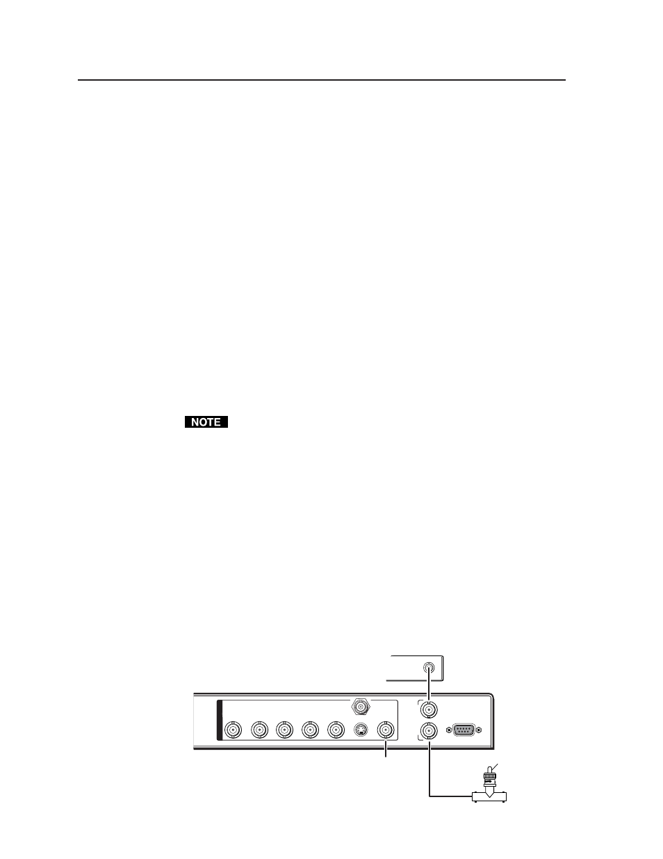
Connect the oscilloscope (“scope”) probe A to the Genlock Out
connector. This will provide the scope’s reference signal. In order to
avoid altering the genlock signal, use the cabling configuration that
will be used in the installation. Either connect the genlock signal cable
from the scope to the next device in the system to be timed, or provide
75 ohm termination at the scope’s genlock output.
O
U
T
P
U
T
S
VIDEO
S-VIDEO
SDI
R/R-Y
G/Y
B/B-Y
H/H-Y
RS-232
/422
G
E
N
L
O
C
K
V
IN
OUT
Timing Source
OUT
To Scope Probe B
To Scope
Probe A
75 ohm Terminator