Installation and operation, cont’d, Input cabling, Figure 2-13 — grounding the transmitter – Extron Electronics TP Transmitters User Guide User Manual
Page 18
Extron TP Transmitters • Installation and Operation
Extron TP Transmitters • Installation and Operation
Installation and Operation, cont’d
2-20
Ground the transmitter using any of the following methods:
•
Connect a local 15 V power supply to the transmitter.
•
Use STP rather than UTP cable and connectors.
•
TP T 15 HD A and TP T 15HD AV
— Use a 3.5 mm
captive screw connector to connect a ground wire
between the power return pin (figure 2-13) and a
grounding point near the transmitter, such as a grounded
power outlet or an equipment rack.
•
TP T 468 only
— Connect a ground wire between the
power return pin (figure 2-13) of the 3.5 mm, 2-pole
direct-insertion captive screw connector on the rear of the
transmitter and a grounding point near the transmitter.
Return
Grounding Point
near Transmitter
TP T 15HD A and
TP T 15HD AV
TP T 468
N/C
Figure 2-13 — Grounding the transmitter
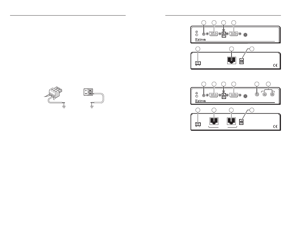
Input cabling
Computer video and PC audio
The TP T 15HD A (figure 2-14), the TP T 15HD AV
(figure 2-15), and the TP T 468 (figure 2-16) all accept and
transmit computer video and PC audio. These transmitters can
also accommodate component video, S-video, or composite
video if input on the R, G, and B pins of the 15HD connector
using an Extron SYM BNCF/0.5 6" (15 cm) cable,
part #26-531-01.
H-SHIFT
TP T 15HD A
AUDIO
DDSP
SP
ARE
BUFFERED
COMPUTER
INPUT
LOCAL MONITOR
OUTPUT
ID PIN 4
ID PIN 11
POWER
15V .5A DC
2
1
4
3
11
9
5
Figure 2-14 — Installation features, TP T 15HD A
PC
H-SHIFT
TP T 15HD AV
AUDIO
VIDEO
AUDIO
L
R
BUFFERED
COMPUTER
INPUT
LOCAL MONITOR
ID PIN 4
ID PIN 11
POWER
15V .5A DC
DDSP
SP
ARE
OUTPUTS
AV
COMPUTER
2
6
1
4
3
11
9
10
5
7
Figure 2-15 — Installation features, TP T 15HD AV
2-21