Installation and operation, cont’d, Video dip switch, Audio jumpers – Extron Electronics TP Transmitters User Guide User Manual
Page 10
Extron TP Transmitters • Installation and Operation
Extron TP Transmitters • Installation and Operation
Installation and Operation, cont’d
2-5
Video DIP switch
The TP T 468 can be configured to transmit component video,
S-video, or composite video. To configure the TP T 468
for RGB video, set DIP switch 2 on the back of the
transmitter to Off. For any other video format set the
switch to On.
Audio jumpers
Older (unmodified) transmitters and receivers are fully
compatible with each other but not with the TPX 88 A
twisted pair matrix switcher.
Redesigned (modified) transmitters and receivers are
fully compatible with each other and with the TPX 88 A.
They can also be jumpered to be compatible with the
older (unmodified) receivers and transmitters but not
the TPX 88 A.
Redesigned (modified) transmitters and receivers have an
identifying label.
The audio that is associated with the composite video link of
TP T 15HD AV transmitters is transmitted on wire pair 3 and 6.
This configuration is compatible with redesigned TP receivers
and the TPX 88 A.
If you intend to match this transmitter with an older,
unmodified TP receiver, and do not plan to include a TPX 88 A
in your system, you can set the transmitter to send the audio on
wire pair 7 and 8, to be compatible with an older TP receiver, by
shifting internal jumpers as follows:
2-4
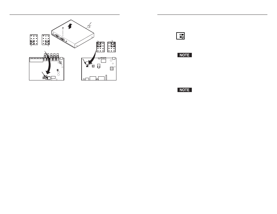
TP T BNC DA4
Remove 5 BNC hex nuts.
Component,
S-video,
Composite
U31
J12
J11
J1
J2
1
1
1
1
Component,
S-video,
Composite
1
1
1
1
RGB
1
1
1
1
1
1
1
1
RGB
TP T 15HD A
Remove 6
screws.
TP
T 15HD A
H-SHIFT
BU
FFERED
COMPUTER
INPUT
AUDIO
ID PIN 4
ID PIN 11
LOCAL MONIT
OR
Lift cover
straight up.
TP T BNC DA4
TP T 15HD A and TP T 15HD AV
Figure 2-1 — Video jumper configuration
2
.
TP T BNC DA4
: Using an Extron BNC extraction tool (part
#100-096-01) or a 14 mm, deep well socket with thin walls,
remove the five hex nuts securing the BNC connectors to
the rear panel. Slide the cover forward until the cover
clears the BNC connectors
3
.
Lift the cover off.
4
.
TP T 15HD A and TP T 15HD AV
:
Locate J1 and J2 on the
printed circuit board. See figure 2-1.
a
.
For RGB video
, ensure that pin 2 is jumpered to
pin 3 on both jumper locations.
b
.
For any other video format
, ensure that pin 1 is
jumpered to pin 2 on both jumper locations.
TP T BNC DA4
:
Locate J11 and J12 on the printed circuit
board. See figure 2-1.
a
.
For RGB video
, ensure that pin 2 is jumpered to
pin 3 on both jumper locations.
b
.
For any other video format
, ensure that pin 1 is
jumpered to pin 2 on both jumper locations.
5
.
Replace the cover and reinstall the screws.
1
O N
2