For ir communication, Ir connection, Figure 37. ir emitter cable connection – Extron Electronics PVS 405D User Guide User Manual
Page 55
PVS 405D • Connector Wiring
49
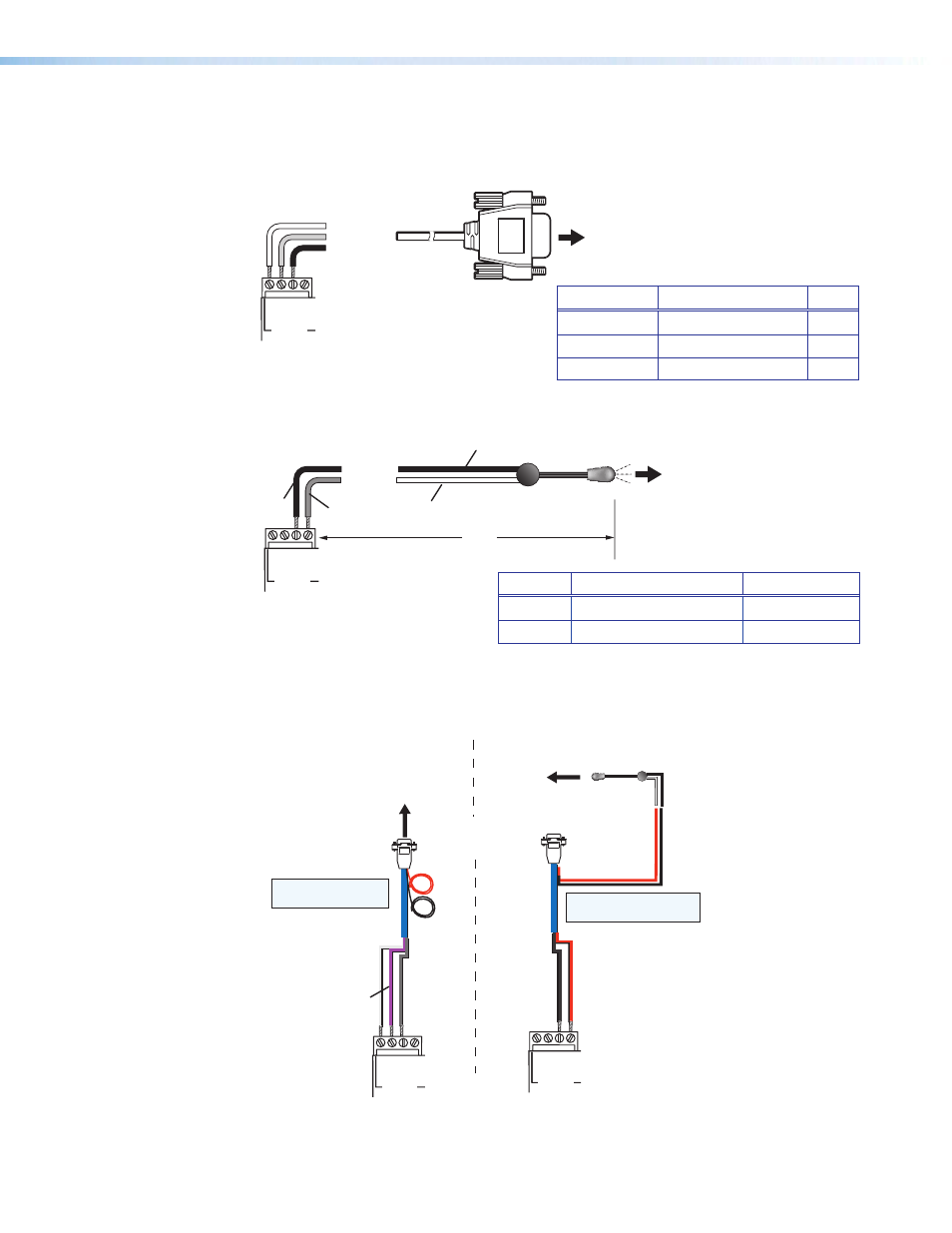
For IR communication
Connect the IR/RS‑232 projector communication cable for either RS‑232 or IR projector
control.
MLC 104 IP Plus
Right Side Panel
Ground
Receive (Rx)
Transmit (Tx)
GR
O
UND
IR OU
T
Tx
Rx
DISPLAY
RS-232/IR
RS-232 to projector
RS-232 connection
Figure 35.
RS-232 Connection to Projector
MLC 104 IP Plus
Right Side Panel
To projector
Ground
IR Signal
Unidirectional IR Output
via White Striped Wire
IR Emitter
100'
(30.5 m)
GR
O
UND
IR OU
T
Tx
Rx
DISPLAY
RS-232/IR
IR connection
Black
Black
Red
Figure 36.
IR Connection to Projector
Connect the MLC to the projector with an RS‑232 cable or IR emitter cable, as
appropriate
Red
Black
Projector
MLC IR/RS-232
Comm Cable
IR Emitter
Connecting IR Cable
White
(or striped)
Black
Red
Black
9-Pin Female
White
Violet
Shield
MLC 104 IP Plus
Connecting RS-232 Cable
Projector
GROUND
IR OU
T
Tx
Rx
DISPLAY
RS-232/IR
GROUND
IR OU
T
Tx
Rx
DISPLAY
RS-232/IR
NOTE: Red and black
not used.
NOTE: White, violet, and
shield not used.
Figure 37.
IR Emitter Cable Connection
Terminal
RS-232 Cable color Pin
Tx
White
2
Rx
Violet
3
Ground
Shield
5
Terminal IR/RS-232 Cable color IR Cable color
Ground
Black
Black
IR Signal
Red
White/Black