Front panel dip switch settings, Installation, connection, and settings, cont’d, Front panel dip switch settings ettings – Extron Electronics SCS 300 User Guide User Manual
Page 17
SCS 300 • Installation, Connection, and Settings
2-10
Installation, Connection, and Settings, cont’d
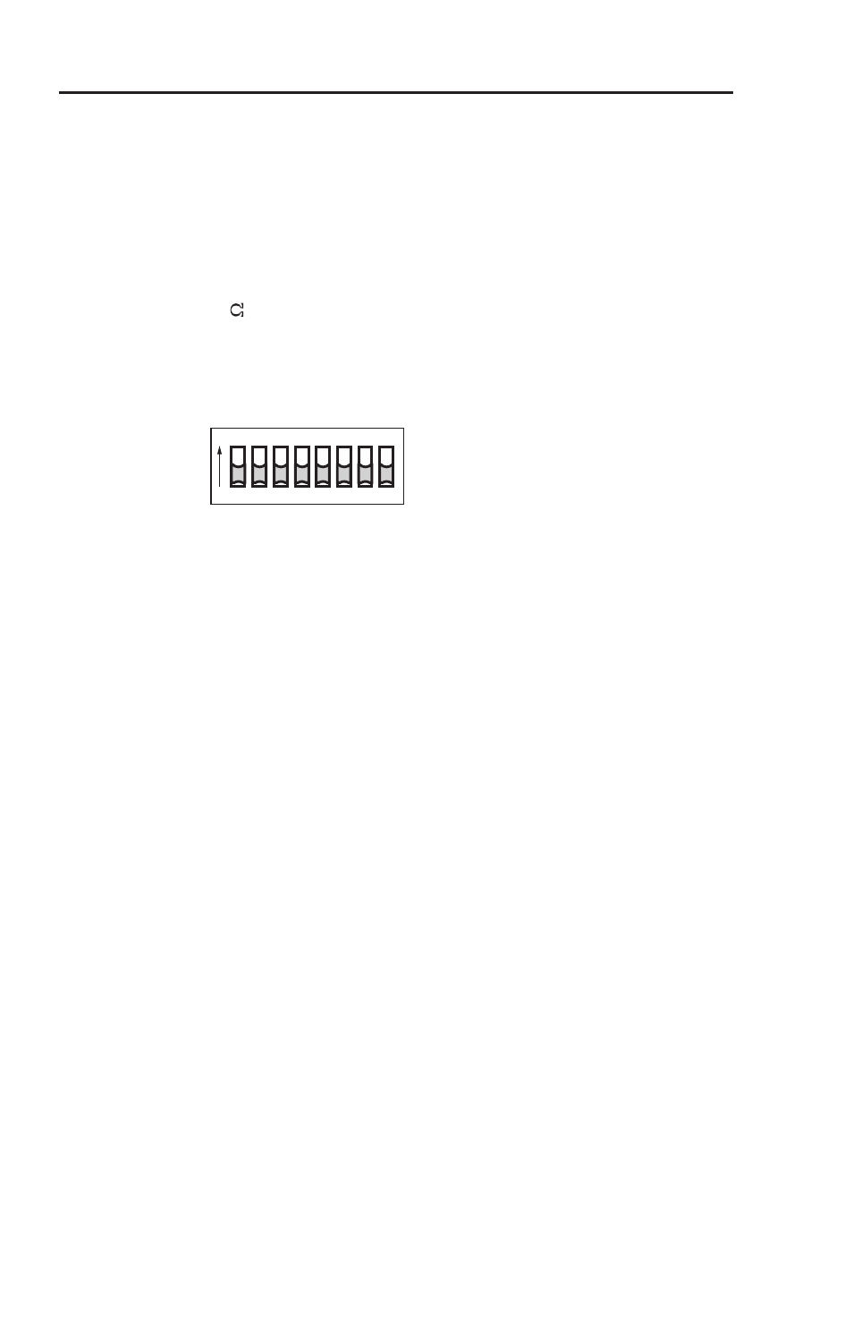
Up position = On
Down = Off
Default = all Off
Front Panel DIP Switch Settings
ettings
The bank of eight DIP switches allows the user to control sync
input termination, sync polarity, output sync format, and
serration pulses, or to disable all sync processing. Switches
furthest to the right takes the highest priority. Set each switch as
desired, in the order they are listed:
INPUT SYNC 10K
FORCE NEG SYNC
COMP SYNC OU
T
SOG OU
T
RsGsBs OUT
SERR REMO
VA
L
NO SYNC PR
OC
SP
ARE
ON
OFF
ON
1 2 3 4 5 6 7 8
Settings for the DIP switches on the SCS 300:
Switch 1
: On = 10k ohm sync input termination
Off = 510 ohm sync input termination
Switch 2
: On = Force negative sync polarity on output
Off = Sync polarity follows input
Switch 3
: On = Enable composite sync output
Off = Disable composite sync output
Switch 4
: On = Sync on green output
Off = Disable sync on green output
Switch 5
: On = Enable RsGsBs (sync on all)
Off = Disable RsGsBs
N
When switch #s 3, 4, and 5 are in the off position,
Horizontal and Vertical sync is on.
Switch 6
On = Disable (remove) serration pulses
Off = Enable (pass) serration pulses
Switch 7
: On = Disables sync processing
Off = Normal sync processing
N
If switch #7 is in the on position, it disables all switches
except for switch #1, and deactivates all sync processing
and timing changes. However, sync edges will still be
reshaped.
Switch 8
: Spare