Rear panel features and connection, Figure 2-7 — rear panel features, Figure 2-8 — wiring the power connector – Extron Electronics SCS 300 User Guide User Manual
Page 14
SCS 300 • Installation, Connection, and Settings
2-7
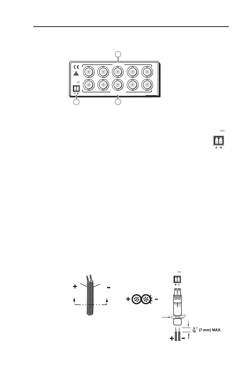
Rear Panel Features and Connection
The rear panel has three main features:.
POWER
12V
0.4A MAX
INPUT
R
G
B
H/HV
V
SCS 300
OUTPUT
1
2
3
`
Figure 2-7 — Rear Panel features
a
Power connection point — This dedicated female,
3.5mm, 2-pole captive screw connector enables
connection of the 12 VDC external power supply. Wire
the power supply cord into the supplied male orange
connector as shown in figure 2-8.
C
Power supply voltage polarity is critical. Incorrect
voltage polarity can damage the power supply and
the SCS 300. Identify the power cord negative lead
by the ridges on the side of the cord (figure 2-8).
C
The length of the exposed (stripped) copper wires
is important. The ideal length is 5/16” (7 mm).
Longer bare wires can short together. Shorter wires
are not as secure in the captive screw connectors
and could be pulled out.
N
Do not tin the stripped power supply leads before
installing the captive screw connector. Tinned wires are
not as secure in the captive screw connector and could be
pulled out. Use the supplied tie warp to strap the wires to
the connector.
Power Supply
Output Cord
Orange Captive
Screw Connector
SECTION A–A
Ridges
Smooth
A
A
Tie Wrap
POWER
12V
0.4A MAX
Figure 2-8 — Wiring the power connector
POWER
12V
0.4A MAX