Installation, connection, and settings, cont’d, Rgsb/rsgsbs, Rgbs – Extron Electronics SCS 300 User Guide User Manual
Page 15: Rgbhv
Installation, Connection, and Settings, cont’d
SCS 300 • Installation, Connection, and Settings
2-8
Insert the wired connector into the female, 2-pole captive screw
connector (
a
) marked "power".
C
When using a compatible power source from the
projector, verify that it is 12 VDC positive.
b
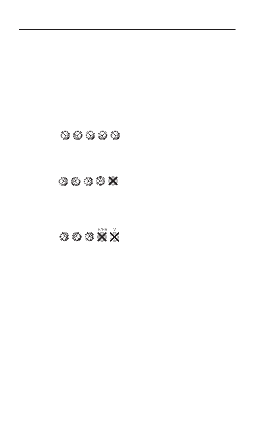
Input connectors — Non-interlaced video signal input is made
on these five female BNC connectors, labeled Input. Connect
the input devices' video signal cables to the BNC connectors,
ensuring the correct cable matches the labeled input connector.
RGBHV
– If all cables are connected, the sync input is separate
horizontal and vertical.
RGBS
– If the H/HV (composite sync) cable is connected, the
input is composite sync.
RGsB, RsGsBs
– If coax cables are connected and terminated
(75 ohms) to the red, green, and blue channels only, the
input is sync on green.
c
Output connectors — The converted video signal output is
carried on these five female BNC connectors, labelled Output.
Use BNC cables to attach the output connectors to a projector or
other display device. This output is simultaneous and identical
to the output on the 15-pin HD connector on the front panel.
RGsB
— When the DIP switch (SOG Out) is set to On, and
terminated (75 ohms) coax cables are connected to red,
green, and blue channels only, the output is sync on green.
RsGsBs
— When the DIP switch (RsGsBs Out) is set to On, and
terminated (75 ohms) coax cables are connected to red,
green, and blue channels only, the output is sync on all.
RGBS
— When the DIP switch (Comp sync out) is set to On,
and the H/HV cable is connected, the output is composite
sync.
RGBHV
— When DIP switches 3, 4, and 5 are set to Off, and all
cables are connected, the sync output is separate horizontal
and vertical.
RGsB/RsGsBs
R
G
B
RGBS
R
H/HV
G
V
B
RGBHV
R
H/HV
G
V
B