Remote control, Reset, Power and fans – Extron Electronics MTPX Plus 6400 Series Setup Guide User Manual
Page 10: Remote control reset power and fans
h
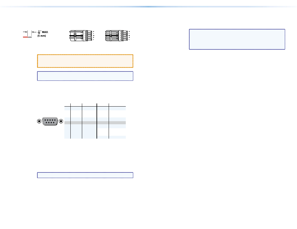
Local audio outputs — Connect audio devices, such as audio
amplifiers or powered speakers to these 3.5 mm, Mono Audio
(local audio) Outputs 5-pole captive screw connectors to receive
unamplified, mono line level audio.
Ring
Sleeve(s)
Tip
Tip
Ring
Sleeve(s)
Tip
Tip
Unbalanced Stereo Output
Balanced Stereo Output
NO GROUND HERE.
NO GROUND HERE.
LR
Do not tin the wires!
Figure 5.
Audio Output Connector Wiring
CAUTION:
For unbalanced audio, connect the sleeves to the
ground contact. DO NOT connect the sleeves to
the negative (-) contacts.
NOTE: Each local output has a volume control. See "
” on page 18.
Remote Control
i
Remote RS-232/RS-422 port — If desired, connect a control system
or computer to the rear panel Remote RS-232/RS-422 port.
RS-232 Function
Pin
Function
1
2
3
4
5
6
7
8
9
—
Tx
Rx
—
Gnd
—
—
—
—
Not used
Transmit
Receive
Not used
Ground
Not used
Not used
Not used
Not used
—
Tx–
Rx–
—
Gnd
—
Rx+
Tx+
—
Not used
Transmit (–)
Receive (–)
Not used
Ground
Not used
Receive (+)
Transmit (+)
Not used
RS-422
5
1
9
6
Figure 6.
Remote RS-232/RS-422 Output Connector Wiring
j
Ethernet port — If desired, connect a network WAN or LAN hub, a
control system, or a computer to the Ethernet RJ-45 port.
Network connection — Wire as a patch (straight) cable.
Computer or control system connection — Wire the interface
cable as a crossover cable.
NOTE: The factory default IP address is 192.168.254.254.
Reset
k
Reset button — Initiates four levels of reset of the matrix switcher.
For different reset levels, press and hold the recessed button while
the switcher is running or while you power up the switcher.
See the MTPX Plus 6400 Series User Guide, available on the Extron
DVD or at
www.extron.com
.
Power and Fans
l
Power connectors — Plug the switcher into two grounded AC
sources.
NOTE: For reliability, connect the power cord from the
Redundant power connector to either an
uninterruptible power source or to a power source
that is completely independent of the primary power
source.
m
Primary and Redundant power supply indicator LEDs —
Green — Indicates that the associated power supply is operating
within normal tolerances.
Red — Indicates that the associated power supply is operating
outside the normal tolerances or has failed. See "
Installing a Power Supply Module
" on page 47 to replace the
power supply.
n
Fans — See "
10
MTPX Plus 6400 • Installation
11
MTPX Plus 6400 • Installation