Extron Electronics MTP Series User Guide User Manual
Page 20
MTP Series • Installation
14
f
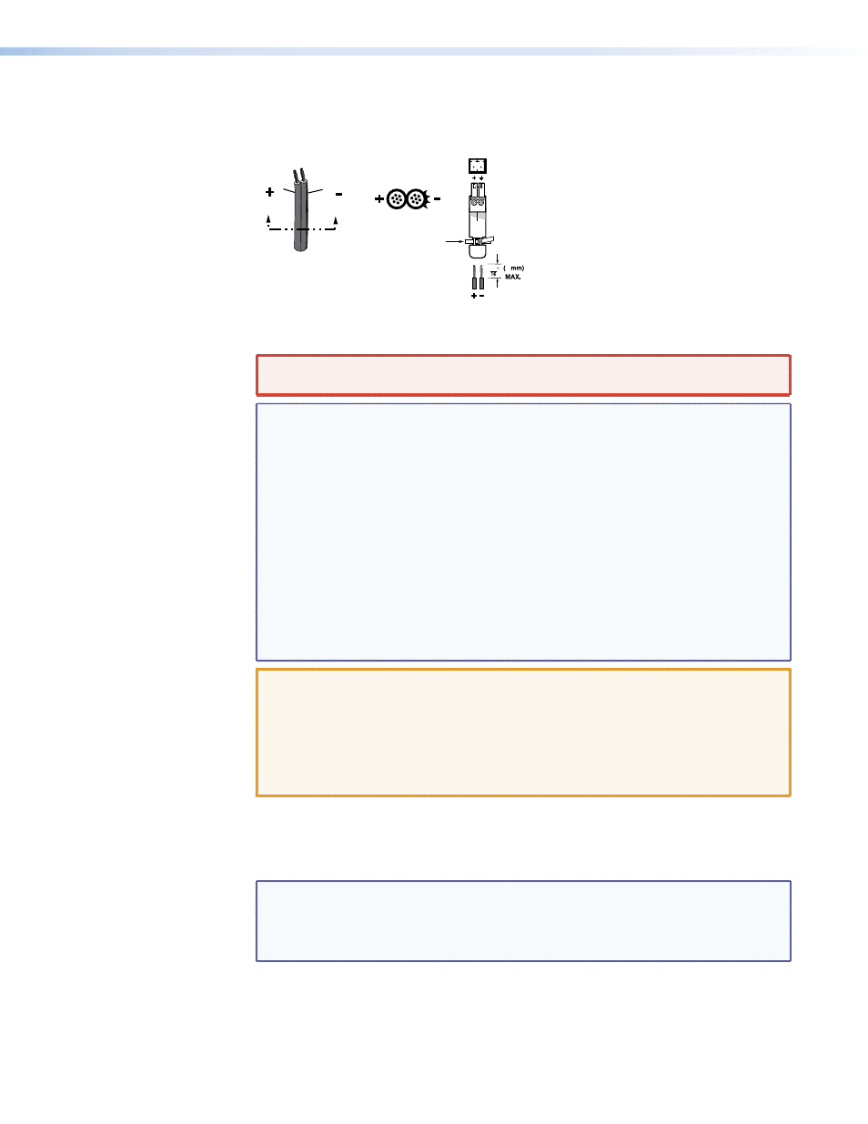
Power connector — Plug the external 12 VDC power supply into this 2-pole captive
screw connector on both the transmitter and the receiver.
shows how to wire
the connectors.
Power Supply
Output
Cord
Captive Screw Connector
SECTION A–A
Ridges
Smooth
A
A
Tie Wrap
3
5
Figure 19.
Power Connector Wiring
WARNING: The two power cord wires must be kept separate while the power
supply is plugged in. Remove power before wiring.
NOTES:
•
If the transmitter and receiver are either older generation units or jumper
configured to the stereo audio position (compatible with the older
units), only a single device needs to be powered in a two-unit system
(see “
Signal Jumpers for Generational Compatibility”
on page 3).
The device connected to the power supply, in turn, provides power to its
counterpart.
•
If the transmitter and receiver are separated by greater than 200 feet
(61 meters) of STP/UTP/FTP cable, connect a power supply to both units.
This remote power application is only available in stereo mode, not mono
mode.
•
Do not tin the stripped power supply leads before installing the captive
screw or direct insertion connector. Tinned wires could be pulled out
because they are not as secure in the captive screw and direct insertion
connectors.
CAUTIONS:
•
Power supply voltage polarity is critical. Incorrect voltage polarity can
damage the power supply and the MTP. Identify the power cord negative
lead by the ridges on the side of the cord (see
).
•
The length of the exposed (stripped) copper wires is important. The
ideal length is 3/16 inches (5 mm). Longer bare wires can short together.
Shorter wires are not as secure in the captive screw connectors and
could be pulled out.
To verify the polarity before connection, plug in the power supply with no load and
check the output with a voltmeter.
Use the supplied tie-wrap to strap the power cord to the extended tail of the connector.
NOTE: Your transmitter/receiver pair may have shipped with a blue captive screw
connector. This blue connector can be plugged into either a blue or an
orange power receptacle.
The blue connector does not have an extended tail or the included tie-wrap.
Alternatively, an optional Extron PS 124 Universal 12 VDC Power Supply (part number
60-1022-01) can power multiple Extron 12 VDC devices using only one AC power
connector.
g
Power LED — Indicates power is applied to the MTP.