Power connection (all models), Tp cable termination, Figure 18. power connections and indicators – Extron Electronics MTP Series User Guide User Manual
Page 19
MTP Series • Installation
13
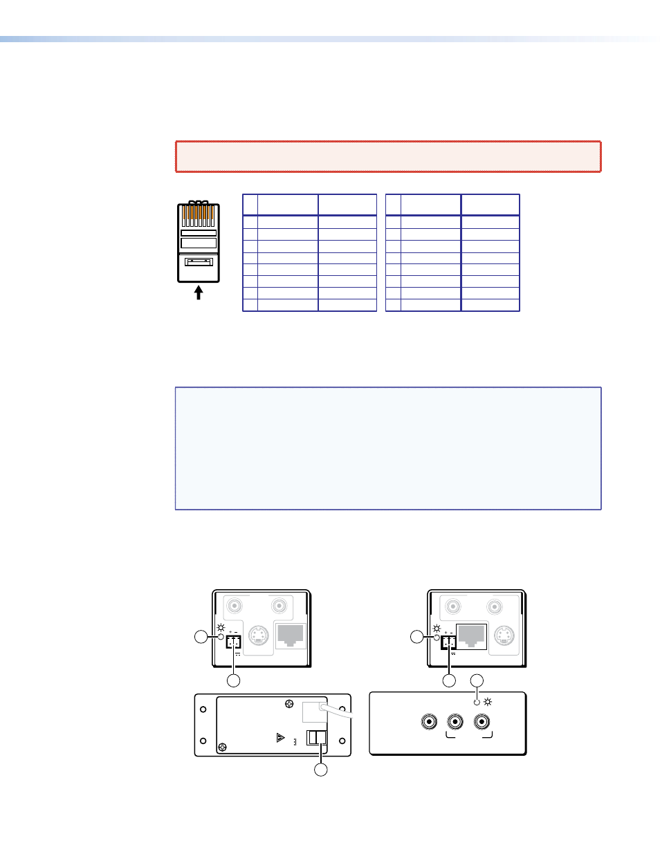
TP cable termination
details the recommended termination of TP cables with RJ-45 connectors in
accordance with the TIA/EIA T 568A or TIA/EIA T 568B wiring standards. You can use either
standard, but ensure that you use the same standard on both cable ends.
WARNING: Damage may occur to the unit if TP cables are miswired as crossover
cables.
A cable that is wired as T568A at one end
and T568B at the other (Tx and Rx pairs
reversed) is a "crossover" cable.
A cable wired the same at both ends is
called a "straight-through" cable, because
no pin/pair assignments are swapped.
12345678
RJ-45
Connector
Insert Twisted
Pair Wires
Pins:
Crossover Cable
Straight-through Cable
Pin
1
2
3
4
5
6
7
8
Wire color
White-green
Green
White-orange
Blue
White-blue
Orange
White-brown
Brown
Wire color
T568A
T568B
End 1
End 2
End 1
End 2
White-orange
Orange
White-green
Blue
White-blue
Green
White-brown
Brown
Pin
1
2
3
4
5
6
7
8
Wire color
White-orange
White-green
Blue
White-blue
White-brown
Brown
Wire color
T568B
T568B
White-orange
Orange
Orange
White-green
Blue
White-blue
Green
Green
White-brown
Brown
Figure 17.
TP Cable Termination
NOTES:
•
Enhanced Skew-free A/V cable is not recommended for Ethernet/LAN
applications.
•
This cable is specially designed for compatibility with Extron Twisted Pair
products, wired using the TIA/EIA 568 A standard.
•
The green, brown, and blue pairs of this cable have virtually identical lengths
and should be used to transmit the video signals.
•
The orange pair of this cable has a different length and should not be used
to transmit the video signals.
Power Connection (All Models)
to identify the power connections and indicators and to identify the panel
screws.
MTP Transmitters
MTP Receivers
MTP AAP Transmitters
INPUT
MTP T SV A RCA
OUTPUT
S-VIDEO
L
R
OUTPUT
MTP R SV A RCA
INPUT
S-VIDEO
R
L
12V
0.5a MAX
12V
0.5a MAX
AUDIO IN
VIDEO
IN
L
R
MTP T AV
12V
0.5A
MAX
OUTPUT
PO
WER − +
6
7
6
6
7
7
Figure 18.
Power Connections and Indicators