Programmer’s guide, Rs-232 link, Ethernet link – Extron Electronics ISM 182 User Manual
Page 46
Integration Scaling Matrix Switcher • Programmer’s Guide
4-2
Programmer’s Guide
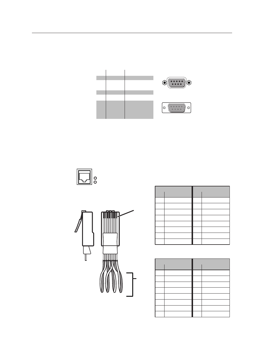
RS-232 Link
The switcher’s rear panel Remote 9-pin D female connector (figure 4-1) can be
connected to the RS-232 serial port output of a host device such as a computer
running the HyperTerminal utility or a control system. This connection makes
software control of the switcher possible.
RS-232
Function
Pin
1
2
3
4
5
6
7
8
9
—
TX
RX
—
Gnd
—
—
—
—
Not used
Transmit data
Receive data
Not used
Signal ground
Not used
Not used
Not used
Not used
5
1
9
5
9
6
Female
Male
1
6
Figure 4-1 — Remote connector pin arrangement
The protocol is 9600 baud, 8-bit, 1 stop bit, no parity, and no flow control.
Ethernet Link
The rear panel Ethernet connector on the switcher can be connected to the an
Ethernet LAN or WAN (figure 4-2). This connection makes SIS
control of the switcher possible using a computer connected to the
same LAN or WAN.
Clip Down
Side
1
1&2
3&6 4&5
7&8
2 3 4 5 6 7 8
1
Pins
2 3 4 5 6 7 8
RJ-45
connector
Patch (straight) cable
Twisted
Pairs
Side 1
Side 2
Pin
Wire color
Pin
Wire color
1
White-orange
1
White-orange
2
Orange
2
Orange
3
White-green
3
White-green
4
Blue
4
Blue
5
White-blue
5
White-blue
6
Green
6
Green
7
White-brown
7
White-brown
8
Brown
8
Brown
Crossover cable
Side 1
Side 2
Pin
Wire color
Pin
Wire color
1
White-orange
1
White-green
2
Orange
2
Green
3
White-green
3
White-orange
4
Blue
4
Blue
5
White-blue
5
White-blue
6
Green
6
Orange
7
White-brown
7
White-brown
8
Brown
8
Brown
Figure 4-2 — RJ-45 connector pinout tables
ETHERNET
LINK
ACT