Installation and operation, cont’d, Ipl t s series • installation 2-8, Ipl t s2 – Extron Electronics IPL T S Series User Guide User Manual
Page 20: Ipl t s6
Installation and Operation, cont’d
IPL T S Series • Installation
2-8
Factory default protocol for the control interface is:
• RS-232
• 9600 baud
• no parity
• 8 data bits
• 1 stop bit
• pacing = 0 ms
• handshaking = off
Communication to an attached device can be done through the IPL T S Series
device’s default Web pages or by using the Extron Simple Instruction Set (SIS
™
)
commands.
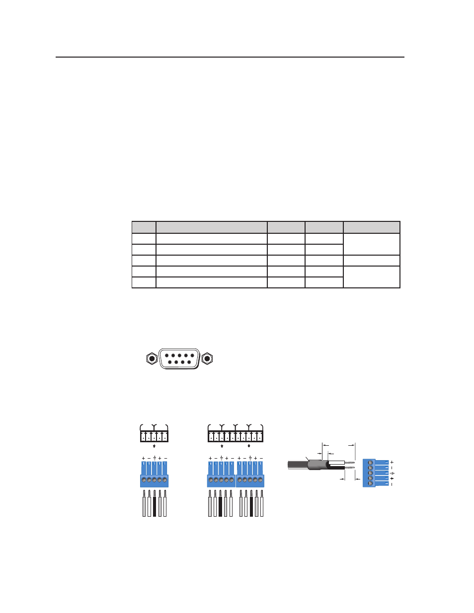
The rear panel 9-pin D connector COM ports have the following pin assignments:
Pin
Function
RS-232
RS-422
RS-485
2
Receive Data/Receive Data -
RX
RX-
Data -
(pins 2 + 3 tied)
3
Transmit Data/ Transmit Data -
TX
TX-
5
Signal Ground
GND
GND
GND
7
Request to Sent/Transmit Data +
RTS
TX+
Data +
(pins 7 + 8 tied)
8
Clear to Send/Receive Data +
CTS
RX+
N
The IPL T S1 uses RS-232 only.
When using RS-485 with the connections indicated above, Data + can connect
to either pin 7 or pin 8, and Data - can connect to either pin 2 or pin 3.
For RS-232 communication, pins 7 and 8 (RTS and CTS) are optional.
9-Pin D Connector
Pin Locations, Female
5
1
9
6
COM5
TX RX
TX RX
COM6
COM3
TX RX
TX RX
COM4
Tr
ansmit
Recei
ve
Ground
Tr
ansmit
Recei
ve
Tr
ansmit
Recei
ve
Ground
Tr
ansmit
Recei
ve
Tr
ansmit
Recei
ve
Ground
Tr
ansmit
Recei
ve
COM1
TX RX
TX RX
COM2
IPL T S2
Connectors
IPL T S6
Connectors
Heat
Shrink
1/8”
(3 mm)
7/8”
(22 mm)
3/16”
(5 mm) Max.
5-pole Captive Screw
Connector
Figure 2-10 — 5-pin captive screw assignments